Engine - Stalls Within 15 Seconds After A Cold Start
90ford08
^ FUEL SYSTEM - 2.2L TURBO & NON-TURBO - NEW FUEL PRESSURE REGULATOR KIT
^ STALLS - AFTER COLD START - 2.2L TURBO & NON-TURBO
Article No. 90-8-9
FORD: 1989 PROBE
ISSUE: The engine may occasionally stall within 15 seconds after a cold start. This occurs because vacuum is applied to the pressure regulator for 15 seconds after starting the engine to compensate the air/fuel ratio.
ACTION: Install a cold stall pressure regulator kit which reduces the vacuum. Refer to the following procedure for service details.
The cold stall pressure regulator kit consists of:
^ One (1) Control Unit
^ One (1) Three-Way Solenoid Valve
^ One (1) Wire Harness
^ One (1) Vacuum Hose
^ Two (2) Hose Clips (Turbo Only)
^ Five (5) Binding Straps
^ One (1) Vacuum Hose Label
^ One (1) Instruction Sheet
Figure 1:
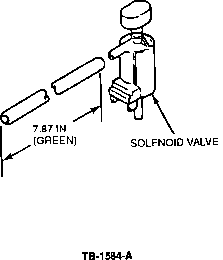
SOLENOID VALVE & VACUUM HOSE INSTALLATION
1. Confirm that the stall condition exists after a cold start in either Park or Drive engagement.
2. Assemble the vacuum hose and solenoid valve from the kit.
3. Disconnect the green vacuum hose from the pressure regulator solenoid valve (green label) and install it on the new solenoid, Figure 1.
Figure 2:
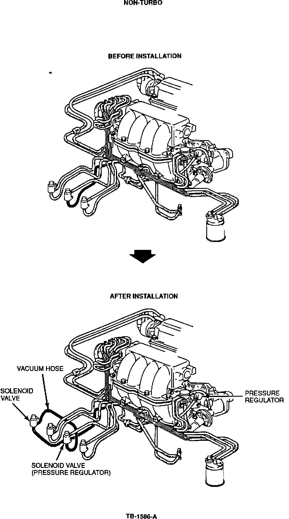
Figure 5:
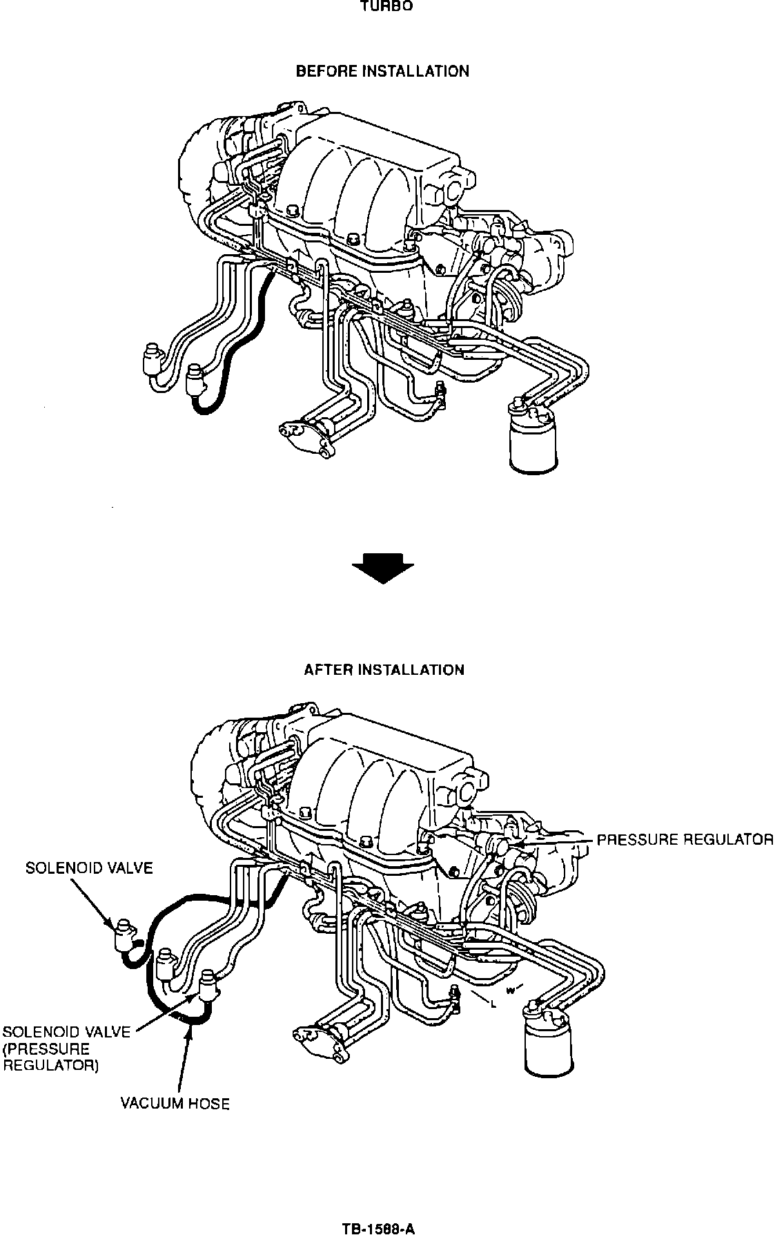
Figure 3:
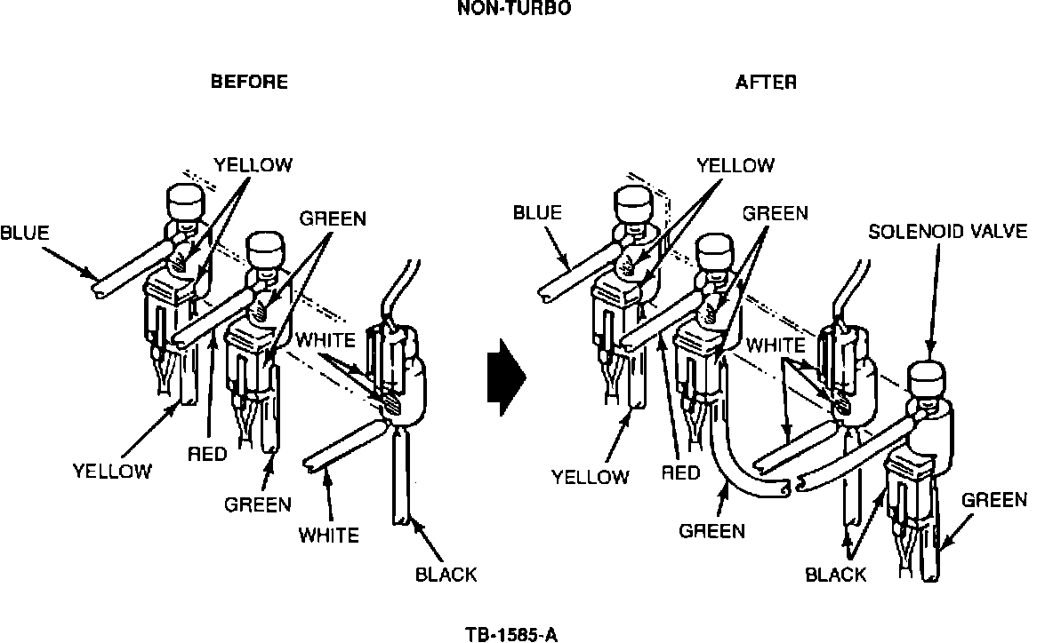
Figure 4:
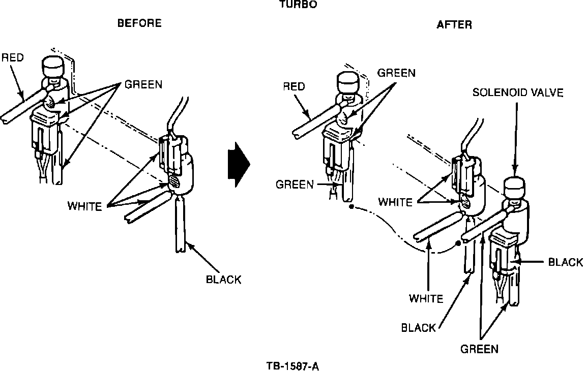
4. Install the new green vacuum hose from the kit between the original solenoid and the new solenoid.
^ See Figures 2 & 3 for non-turbo engines.
^ See Figures 4 & 5 for turbo engines.
5. Install the new vacuum solenoid into the bracket.
Figure 6:
WIRE HARNESS INSTALLATION
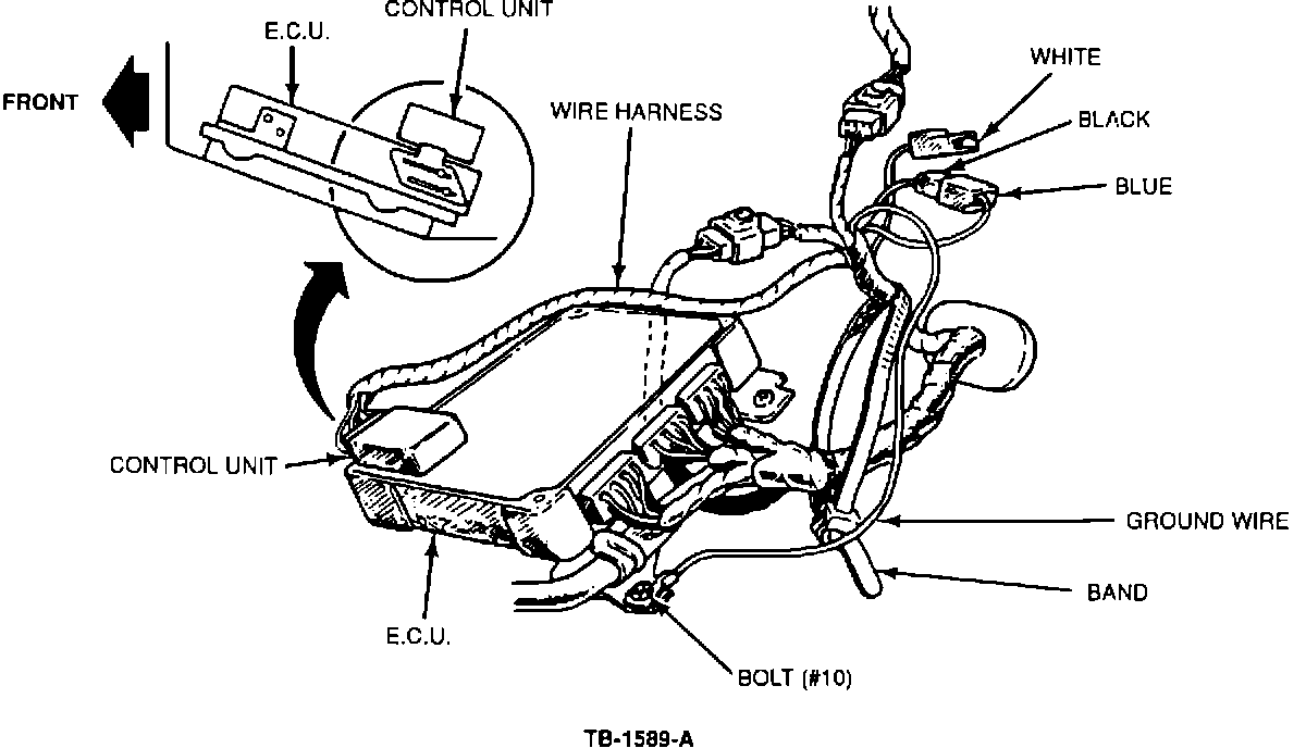
1. Install the control unit from the kit on the MECS electronic controller, Figure 6.
2. Connect the single connectors (black and blue) from the wire harness kit.
3. Connect the harness to the new (small) controller unit.
Figure 7:
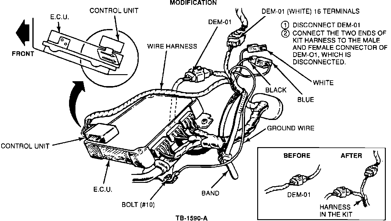
4. Disconnect the white DEM-01 (dash emission) harness. Connect each end of the new harness to each end of the existing white connectors, Figure 7.
5. Install the ground wire with bolt # 10, Figure 7.
6. Attach the wire harness tie straps to secure all wire harnesses.
7. Push the added wire harness through the cowl rubber grommet.
Figure 8:
ENGINE COMPARTMENT MODIFICATIONS
1. Connect the black connector to the new solenoid valve.
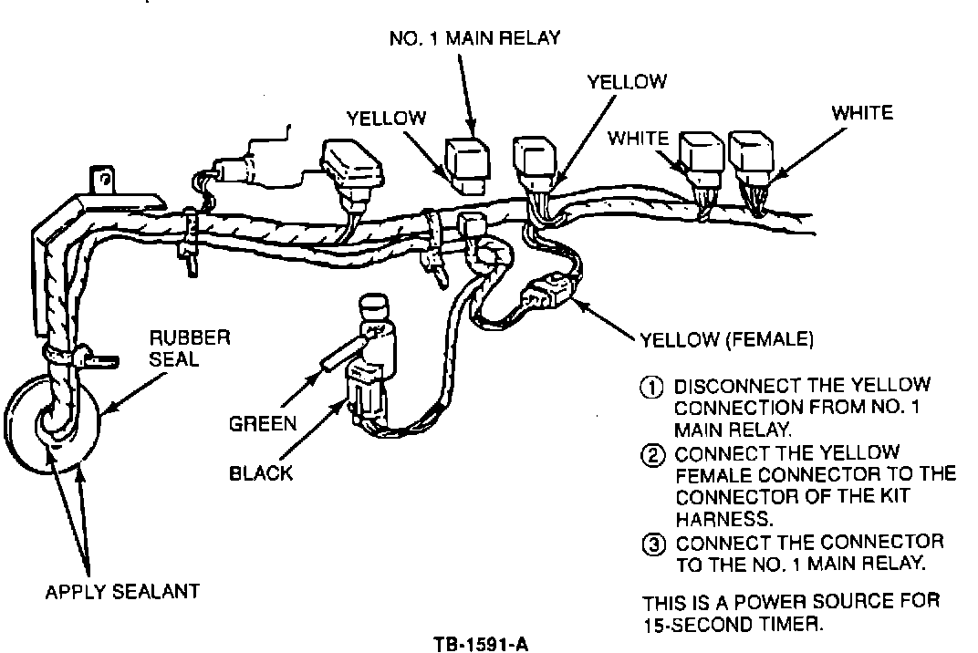
2. Disconnect the yellow wire harness from the No. 1 main relay. Install the yellow connector into the kit harness connector, Figure 8.
Figure 9:
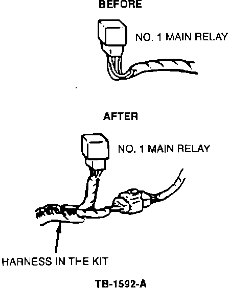
3. Connect the remaining harness connector to the No. 1 relay, Figure 9.
4. Secure the wire harnesses with plastic tie straps.
5. Use silicone sealer aroung the rubber grommet and new wire harness to prevent water entry.
6. Check for vacuum.
a. Attach a vacuum gauge to the fuel pressure regulator valve assembly.
b. Start the engine.
c. Confirm that no vacuum is observed for 15 seconds after the engine is started.
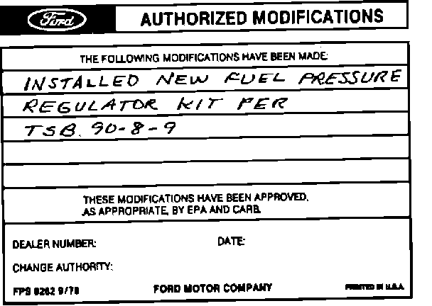
Obtain an Authorized Modifications Decal and list the date, dealer number, and summary of alterations performed. Select a prominent place adjacent to the Vehicle Emission Control Information Decal suitable for installing the Authorized Modifications Decal. Clean the area, install the decal, and cover it with a clear plastic decal shield.
PART NUMBER PART NAME CLASS
F02Z-9C968-BA Pressure Regulator Kit C
OTHER APPLICABLE ARTICLES: None
WARRANTY STATUS: Eligible Under Basic Warranty Coverage
OPERATION DESCRIPTION TIME
900809A Install Kit - 2.2L Non-Turbo 1.0 Hr.
900809A Install Kit - 2.2L Turbo 1.1 Hr.
DEALER CODING
BASIC PART NO. CONDITION CODE
9C968 F6
OASIS CODES: 630100, 630101, 630102, 630103