Quick Test
Fig. 6 Volt/Ohmmeter Installation:

Prior to performing the following tests, a suitable analog volt/ohm meter should be installed on the vehicle as shown, Fig 6.
KEY ON ENGINE RUNNING TEST
Step A
Fig. 7 Quick Test (Step A). 1989 Models:

1. Turn ignition key Off to reset control unit.
2. Ensure visual check of system was performed.
3. Start engine and run at idle.
4. Turn steering wheel to straight ahead position.
5. Activate self-test by turning volt/ohmmeter On.
6. Record all service codes displayed, Fig. 7, then refer to DIAGNOSTIC CHARTS. and SCHEMATIC DIAGRAMS/ELECTRICAL AND ELECTRONIC DIAGRAMS.
Step B
Fig. 13 Quick Test (Step B). 1989 Models:
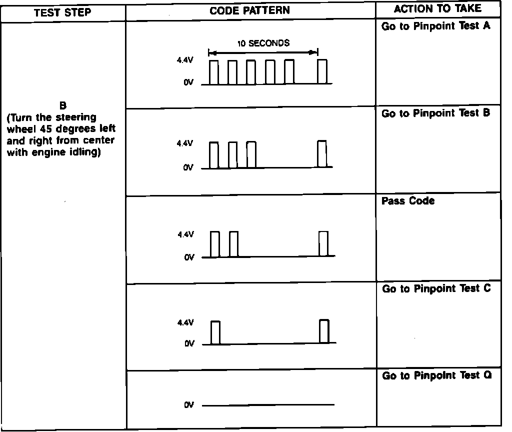
1. Turn ignition key Off to reset control unit.
2. Start engine and run at idle.
3. Turn steering wheel 45 degrees left and right of center with engine idling.
4. Record all service codes displayed, Fig. 13 then refer to DIAGNOSTIC CHARTS. and SCHEMATIC DIAGRAMS/ELECTRICAL AND ELECTRONIC DIAGRAMS.
Step C
Fig. 14 Quick Test (Step C). 1989 Models:
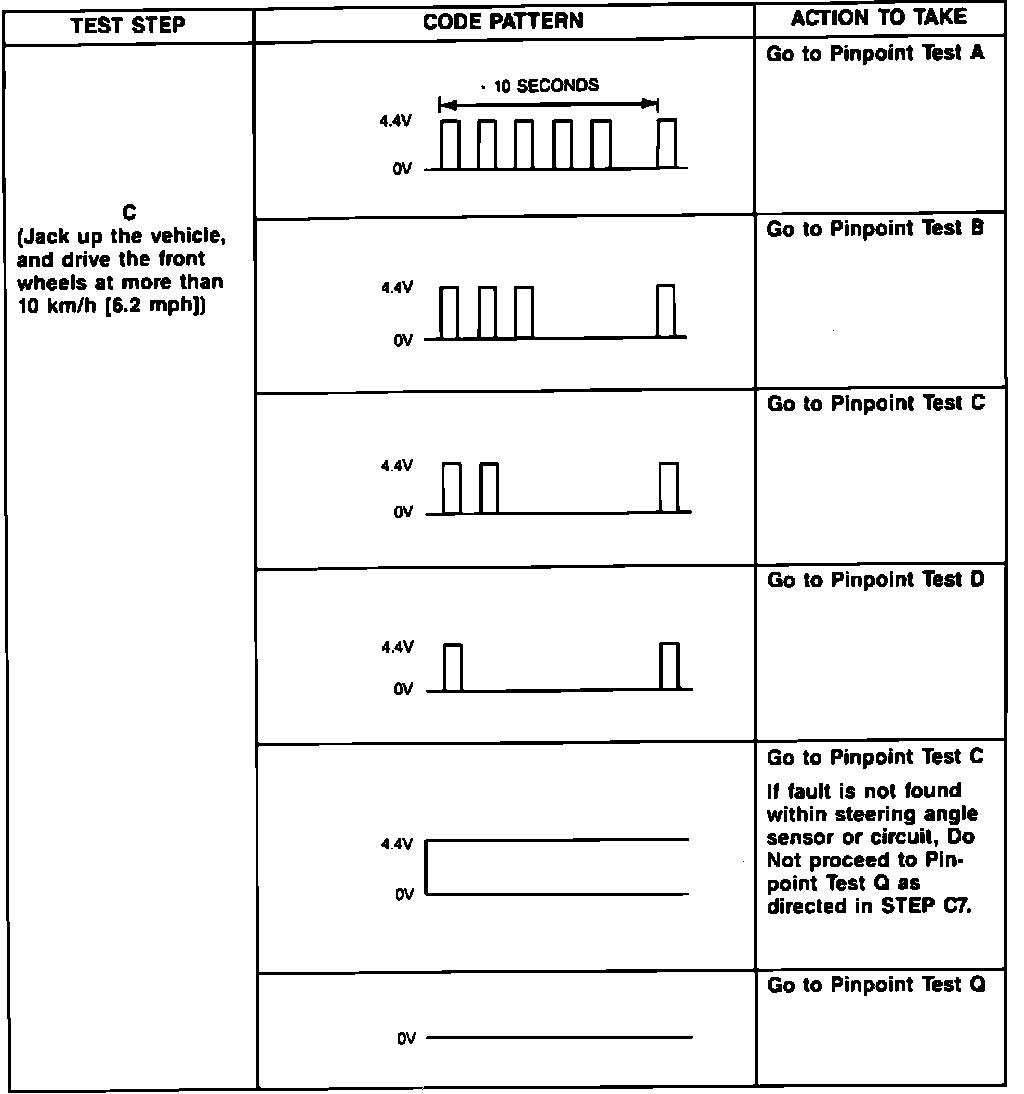
1. Turn ignition key Off to reset control unit.
2. Raise and support vehicle.
3. Start engine and run at idle.
4. Drive front wheels at a speed above 6.2 mph.
5. Record all service codes displayed, Fig. 14, then refer to DIAGNOSTIC CHARTS. and SCHEMATIC DIAGRAMS/ELECTRICAL AND ELECTRONIC DIAGRAMS.
CONTINUOUS TEST
1. Ensure a pass code was indicated in all steps of KEY ON ENGINE RUNNING TEST.
2. With volt-ohmmeter installed, Fig. 6, start engine and run at idle.
3. Tap, move and wiggle sensor connectors and wiring harness while observing volt/ohmmeter, if a fault code is indicated, Fig. 7, 13 and 14. Refer to DIAGNOSTIC CHARTS and SCHEMATIC DIAGRAMS/ELECTRICAL AND ELECTRONIC DIAGRAMS.
4. If no fault code is indicated, reconnect all sensor connectors and terminals.