Antilock Brakes - Removal/Installation Revision
89ford18
SHOP MANUAL - 1989 - SECTION 12-29 - 4-WHEEL ANTI-LOCK BRAKES - REMOVAL AND INSTALLATION PROCEDURE PAGE NUMBER REFERENCE CHANGED
Article No. 89-12A-19
FORD: 1989 PROBE
ISSUE: The Section 12-80 referenced in Step 16 of the 4-Wheel Anti-Lock Brakes Removal and Installation procedure on page 12-29-49 of the 1989 Probe Shop Manual is incorrect.
ACTION: Refer to the page following this TSB for the updated page 12-29-49 showing correct references to pages 12-01-22 and 12-01-23 in Step 16. This information should be inserted in your 1980 Probe Shop Manual, page 12-29-49.
OTHER APPLICABLE ARTICLES: None
WARRANTY STATUS: INFORMATION ONLY
OASIS CODES: 3800
1989
12-29-48 4-Wheel Anti-Lock Brakes 12-29-48
REMOVAL AND INSTALLATION (Continued)
Hydraulic Actuation Unit
Removal
1. Remove the fuel filter assembly. If necessary, refer to Section 24-01.
2. Remove the air filter assembly. If necessary, refer to Section 24-41.
3. Remove the coil assembly. If necessary, refer to Section 23-01.
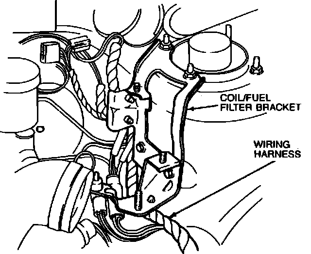
4. Remove the wiring harness from the bottom of the coil and fuel filter mounting bracket.
5. Remove the coil and fuel filter mounting bracket.
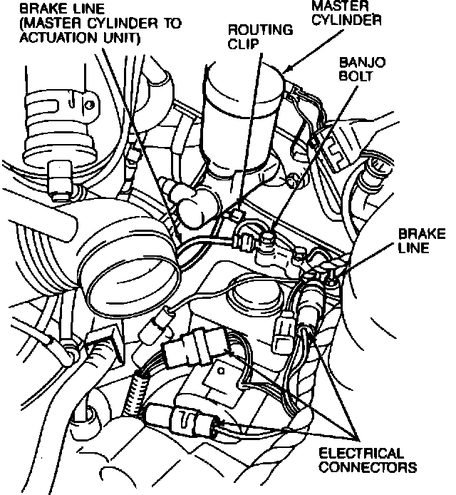
6. Disconnect three electrical connectors.
7. Remove two banjo bolts and four copper washers from the brake lines at the hydraulic actuation unit. Discard the washers.
8. Remove the banjo bolts and four washers from the master cylinder. Discard the washers. Remove the brake lines between the master cylinder and the hydraulic actuation unit.
NOTE: Note the routing of the brake lines to ensure proper installation.
9. Remove routing clip from the brake lines. Using a six inch extension and a 6-point, 10 mm crowfoot wrench, disconnect four brake lines at the hydraulic actuation unit.
NOTE: Note the location of each brake line to ensure proper installation.
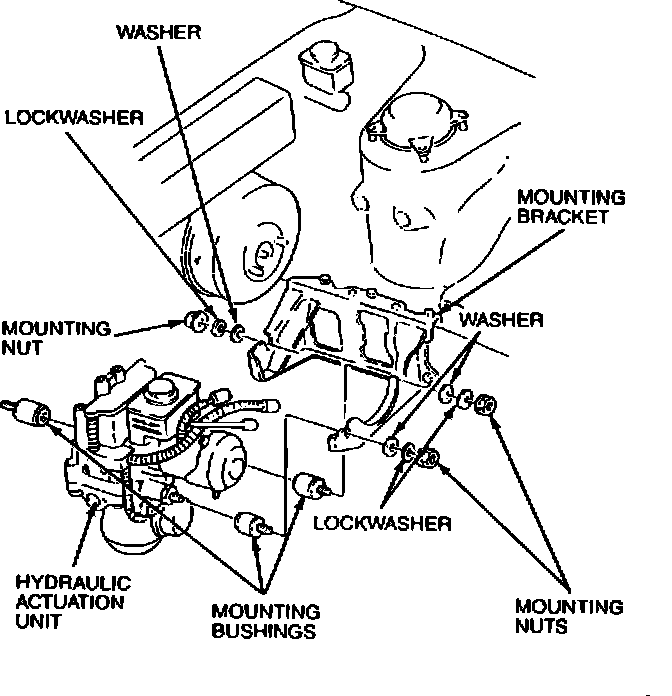
10. Remove three mounting nuts, lockwashers, and washers.
11. Carefully lift the hydraulic actuation assembly from the mounting bracket.
12. Remove three mounting bushings from the hydraulic actuation assembly.
13. If necessary, remove five bolts and the hydraulic unit mounting bracket.
1989
12-29-49 4-Wheel Anti-Lock Brakes 12-29-49
REMOVAL AND INSTALLATION (Continued)
Installation
NOTE: Do not remove the reservoir shipping cap (red) until the hydraulic unit is installed to prevent leaking.
1. Install mounting bracket and live mounting bolts.
2. Install three mounting bushings onto the hydraulic actuation assembly.
3. Carefully position the hydraulic unit in the mounting bracket.
4. Install three washers, lockwashers and nuts onto the mounting bushings. Torque the nuts to 19-25 N-m (14-19 lb.ft.).
5. Connect three electrical connectors. Make sure the connectors lock into place.
6. Using a six-inch extension and a six-point 10 mm crowfoot wrench, install four brake lines to the hydraulic actuation assembly. Torque to 13-22 N-m (9-16 lb.ft.).
7. Position the two brake lines between the hydraulic actuation assembly and the master cylinder.
8. Install two banjo bolts and four new copper washers into the brake lines at the master cylinder. Torque the banjo bolts to 20-29 N-m (14-23 lb.ft.).
9. Install two banjo bolts and four new copper washers into the brake lines at the hydraulic actuation assembly. Torque the banjo bolts to 20-29 N-m (14-23 lb.ft.).
10. Install the coil and fuel filter mounting bracket. Torque nuts to 56-63 N-m (34-46 lb.ft.).
11. Secure wiring harness to the bottom of the coil and fuel filter mounting bracket.
12. Install the coil assembly. If necessary, refer to Section 23-01.
13. Install the air filter assembly. If necessary, refer to Section 24-41.
14. Install the fuel filter assembly. If necessary, refer to Section 24-01.
15. Remove the reservoir shipping cap (red). Install the service cap (black).
16. Bleed the brake system either manually or with a pressure bleeder, Rotunda Number 104-00064. If necessary, refer to Section 12-80, 12-01-22 and 12-01-23.
Wheel Sensor Rotor
Removal-Front
1. Remove the tire and wheel assembly.
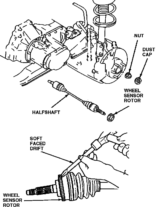
2. Remove the halfshaft. If necessary, refer to Section 15-22.
3. Using a soft faced drift, tap the sensor rotor from the outboard CV joint.
Removal-Rear
1. Remove the tire and wheel assembly.
2. Remove the caliper and anchor bracket. If necessary refer to the procedure in this Section.
3. Remove the rotor. If necessary, refer to Section 12-25.