Fuel Delivery and Air Induction: Description and Operation
Fuel System:
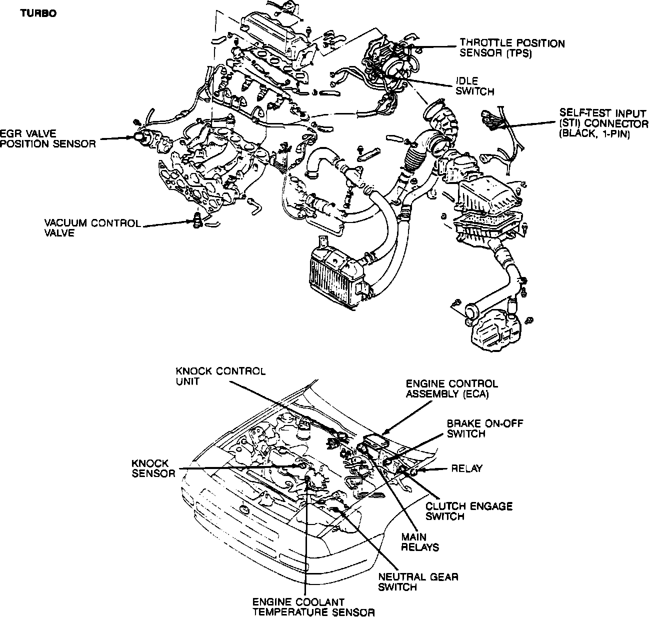
- The Electronic Fuel Injection (EFI) system is a multi-point, pulse fuel injection system. This system utilizes exhaust gas energy to pressurize intake air. It then supplies more than the normal amount of air into the combustion chamber. Resulting in a more fully charged combustion chamber. A higher output and higher torque can be obtained by a turbocharged engine than by a non-turbocharged engine. The turbocharged air induction system and fuel injection system works in conjunction with an electronic engine control system that consists of various sensors, switches and an Electronic Control Assembly (ECA). The ECA interprets the data it receives and computes when and for how long the electrically operated injectors are energized.
- The requirement of fuel is determined from data supplied to the ECA. The Vane Air Flow Meter measures the amount of air being drawn into the turbocharging system. Other sensors and switches are used to measure air temperature, atmospheric pressure, turbine boost, coolant temperature, engine speed, and exhaust oxygen content. The various sensors and switches detect changes in operating conditions and sends signals to the ECA. Permitting proper control over the opening duration of the injectors to maintain optimum exhaust emission control and engine performance
- The fuel delivery system supplies filtered, pressurized fuel to each injector. The system consists of a high pressure electrical fuel pump mounted in-tank, fuel filter, fuel pressure regulator, pulsation damper, fuel injectors, fuel pump switch (located in the Vane Air Flow Meter), fuel pump relay, fuel tank, inertia switch and connecting lines.
- When the engine is in the cranking mode, fuel is supplied to all cylinders simultaneously by providing one injection per crankshaft rotation (two injections per cycle). Therefore one injection period supplies half of the fuel necessary for ideal combustion.
- Between idle and 6,000 rpm, fuel is supplied through a two-group injection by providing one injection per two crankshaft rotations (one injection per cycle). At the completion of the first crankshaft rotation, fuel is supplied to cylinders #1 and #3 by determination of the cylinder identification sensor's signal created by the distributor. After completion of the second crankshaft rotation, fuel is supplied to cylinders #2 and #4.
- To prevent engine overspeeding and possible damage, the fuel supply is cut if the engine speed continues at over 6,000 rpm for approximately 5 seconds. If engine speed momentarily exceeds 6,300 rpm, fuel is cut until engine speed drops to below 5,800 rpm. To prevent turbo overboost, the fuel supply is cut off when the intake manifold pressure exceeds the ECA specified values.