Engine - Vibration/Resonance At Idle
Article No.93-18-8
09/01/93
^ ENGINE TRANSMITS RESONANCE DURING IDLE - VEHICLES WITH 2.0L AND AUTOMATIC TRANSAXLE
^ VIBRATION - RESONANCE DURING IDLE - VEHICLES WITH 2.0L ENGINE AND AUTOMATIC TRANSAXLE
FORD:
1993 PROBE
This TSB article is being republished in its entirety to correct the reference to "engine mount # 3" in Service Procedure Step 1 to read "Engine Mount # 2".
ISSUE:
An engine vibration and resonance may be transmitted into the vehicle's interior during idle because the # 3 engine mount is grounding out.
ACTION:
Check the clearance of the # 3 engine mount and, if necessary, shave off engine mount material which is causing the grounding out condition. Refer to the following service procedure.
INSPECTION - "QUICK CHECKS"
Before performing the repair procedure, do the following "Quick Checks" to determine if the vibration level can be effectively reduced.
1. Compare the vehicle's vibration and resonance to one or more equally equipped vehicles from the dealer inventory. Perform this comparison in DRIVE and REVERSE with the air conditioner on.
2. Perform a visual inspection of engine mount # 3 to verify that it is centered in the bracket. Refer to Step 2 in the service procedures of this article for details.
3. Check the base idle speed at normal operating temperature and, if necessary, set to 700-750 RPM per the service manual.
NOTE:
IF THE RESULTS INDICATE THE LEVEL OF VIBRATION TO BE EQUAL TO OTHER EQUALLY-EQUIPPED VEHICLES AND/OR ENGINE MOUNT # 3 IS CENTERED IN THE BRACKET, PERFORMING THE FOLLOWING REPAIR PROCEDURES WILL NOT REDUCE IDLE VIBRATION. REFER TO THE 1993 PROBE SERVICE MANUAL, SECTION 00-04, FOR ADDITIONAL NVH DIAGNOSIS INFORMATION.
SERVICE PROCEDURE
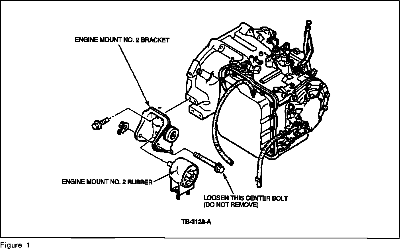
1. Place the vehicle on a hoist. Using a 17 mm socket, loosen (but do not remove) the center bolt that goes through engine mount # 2, Figure 1.
2. Check the clearance of engine mount # 3 against the mounting bracket. There should be clearance between the rubber mount and the bracket with the A/C load on and while in DRIVE or REVERSE. If the rubber mount contacts the bracket proceed as follows:
a. Remove the rubber mount.
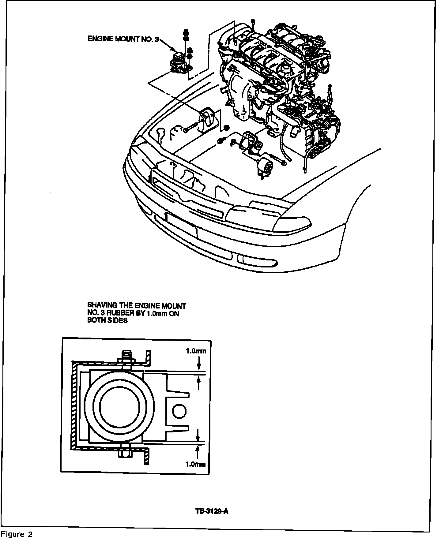
b. With a hacksaw or grinder, shave 1.0 mm of material off both sides of the rubber as shown in Figure 2.
3. Center the engine mount rubber as follows:
a. Remove the air cleaner.
b. Remove the ground connector on engine mount # 4.
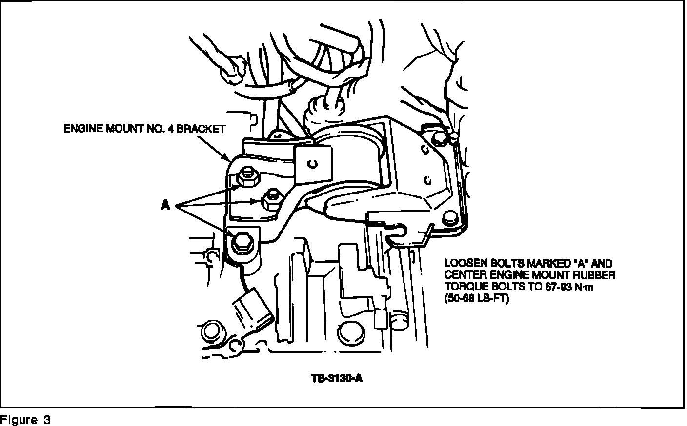
c. Loosen the three bolts marked "A" in Figure 3.
d. Use a pry bar to hold the bracket in place and to center the rubber between the bracket.
e. Retighten the three (3) bolts that were loosened in step "c" above to 50-68 lb.ft. (67-93 N-m).
f. Reconnect the ground connector.
g. Install the air cleaner.

4. Loosen the two (2) nuts holding engine mount # 2 to the engine mount member, Figure 4.
a. Engine mount # 2 will move and align itself.
b. Retighten the two (2) nuts to 55-77 lb.ft. (75-104 N-m), Figure 4.

5. Tighten engine mount # 2 center bolt to 63-86 lb.ft. (86-116 N-m), Figure 5.
6. Run the engine until warm and check for vibration.
a. Check for interference from any components in the engine area that can be a path of vibration from the engine to the body.
b. Ensure that the radiator is centered and the lower radiator mount is fully seated.

7. Check to be sure that the adjustable hood-stop bumpers are in proper position as shown in Figure 6.
a. If not in proper position, align the small bump in the hole on the upper shroud plate, Figure 6.
b. Turn the hood-stop bumpers 90~ counterclockwise to the proper position as shown in Figure 6.
NOTE:
HARDNESS OF THE LEFT AND RIGHT HOOD-STOP BUMPERS IS INTENTIONALLY DIFFERENT. THERE IS A RED MARK IN THE CENTER OF THE RIGHT HAND SIDE HOOD-STOP BUMPER FOR IDENTIFICATION. PART NUMBERS ARE ALSO DIFFERENT.
OTHER APPLICABLE ARTICLES: NONE
SUPERSEDES: 93-12-10
WARRANTY STATUS:
Eligible Under Bumper To Bumper Warranty Coverage
OPERATION DESCRIPTION TIME
931808A Inspect Only 0.2 Hr.
931808B Inspect And Repair 0.8 Hr.
DEALER CODING
BASIC PART NO. CONDITION CODE
6038 41
OASIS CODES:
497000, 597997, 702000, 702100, 703000, 703100