DTC 22: Safing Sensor Output Circuit Short to Battery Voltage
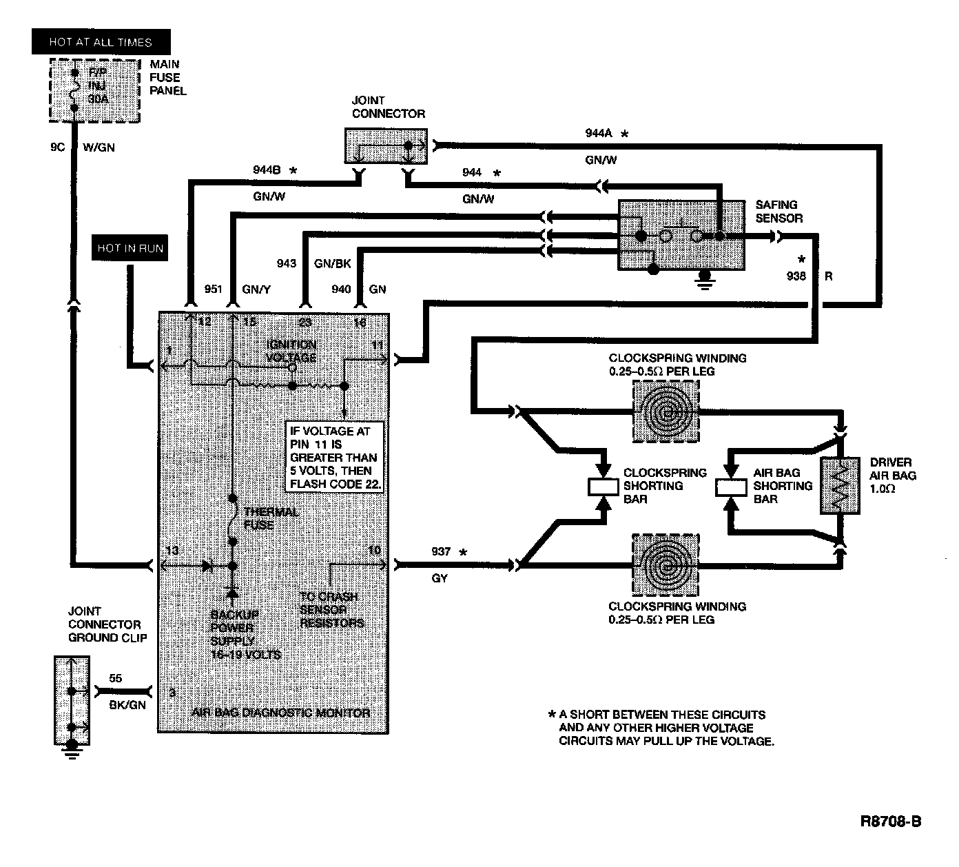
Electrical Schematic:
Pin 11 And 12 Voltage Chart:
Normal Operation
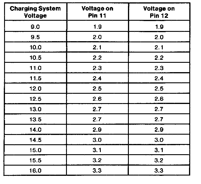
The diagnostic monitor measures the voltage at pins 11 (circuit 944A "GN/W") and 12 (circuit 944B "GN/W"). The voltage at these pins is controlled by two resistors inside the diagnostic monitor (along with the resistors inside the crash sensors - see Normal Operation for DTC 24 for more information). This voltage varies with the charging system voltage as shown in the chart provided.
If the voltage at both of these pins exceed 5 volts, the diagnostic monitor will flash a code 22.
Possible Causes
High voltage at pins 11 and 12 can be caused by the following:
1. A short to power in the wiring harness between circuits 944 "GN/W", 944A "GN/W", 944B "GN/W" or 938 "R" and another wire can cause high voltage on these circuits.
NOTE: The wiring harness leading to the safing sensor carries higher voltage circuits that may short to circuits 944 and 938.
2. A short in the clockspring between circuit 938 and some of the horn or speed control wiring.
3. A short across the normally open contacts of the safing sensor.
NOTE: The voltage at circuits 951 and 943 inside the safing sensor is usually battery voltage or higher. There should be an open circuit across the contacts of the safing sensor if the sensor is operating normally. If the sensor contacts are closed, the voltage on circuits 944 and 938 would be high (at least battery voltage).
4. Vehicle charging system voltage too high. If the generator output voltage is too high (greater than 17 volts), a code 22 may occur.
Pinpoint Test Steps:
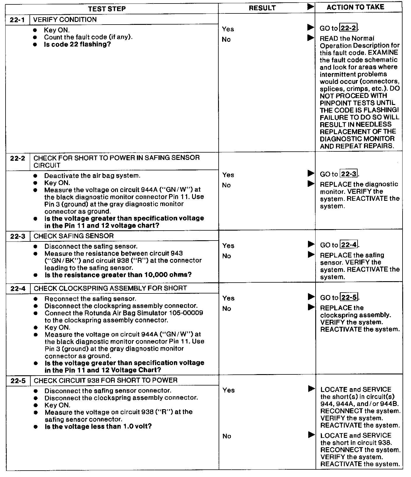
22-1 - 22-5: