Antilock Brakes / Traction Control Systems: Description and Operation
OPERATIONSystem Operation Flow Chart:
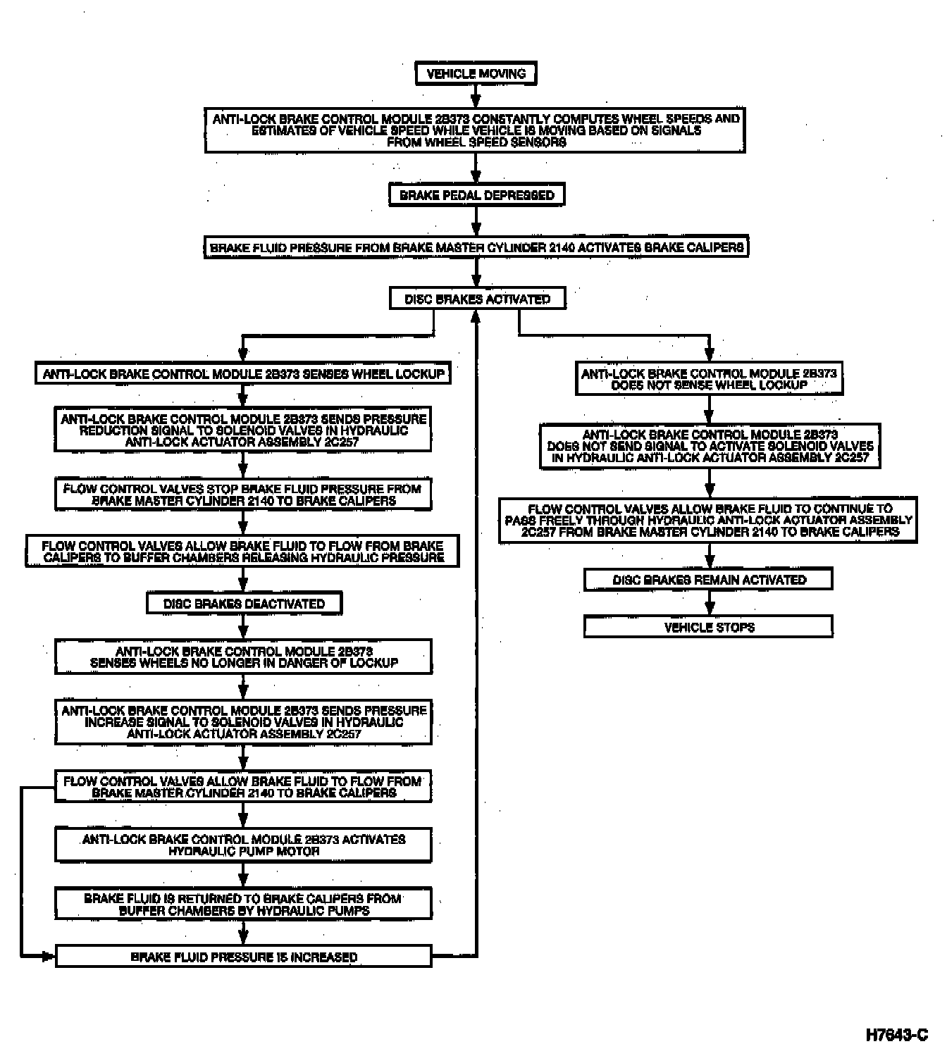
The anti-lock brake system (ABS) functions by releasing and applying fluid pressure to the calipers during special braking conditions. The ABS does not function under normal braking conditions, nor does it affect front-to-rear brake proportioning. When one or more wheels approaches a slip condition, the ABS automatically senses the slip and activates the wheel lock normal function
SYSTEM COMPONENTS

Components of the Anti-Lock Brake System (ABS) include:
- Anti-lock brake control module
- Hydraulic anti-lock actuator assembly
- Anti-lock relay
- Brake master cylinder
- Power brake booster
- Brake pressure control valve
- Front brake anti-lock sensor
- Rear brake anti-lock sensor
- Front brake anti-lock sensor indicator
- Rear brake anti-lock sensor indicator
- Front disc brakes
- Rear disc brakes
ELECTRICAL SYSTEM
The anti-lock brake system (ABS) electrical system consists of a anti-lock brake control module, hydraulic anti-lock actuator assembly and anti-lock relay. These components work together along with the brake anti-lock sensors, brake anti-lock sensor indicators and other brake system components to control braking.
The hydraulic anti-lock actuator assembly consists of four solenoids which control hydraulic fluid flow to each brake caliper. The system has independent front wheel control and select low resistance rear wheel control.
- Front wheel control has two solenoids acting as individual channels. Each front wheel receives independent braking signals, depending on wheel speed.
- Rear wheel control has two solenoids acting as a single channel. The rear wheels receive the same braking signal, depending on the wheel with the lowest resistance.
Thus, this is a four-solenoid, three-channel system.