Brake Proportioning/Combination Valve: Testing and Inspection
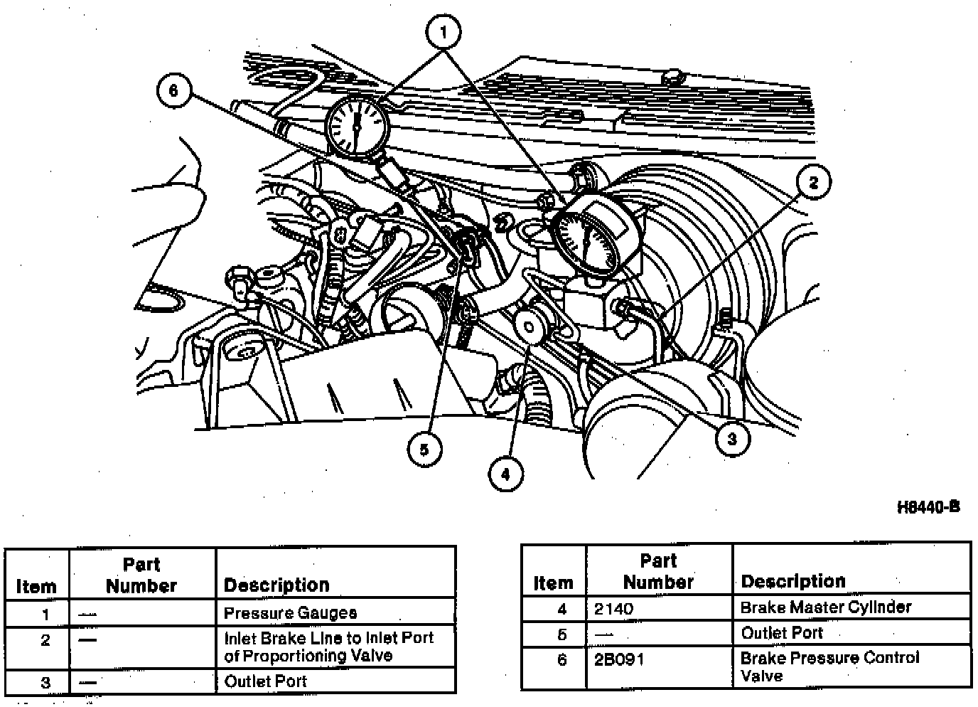
NOTE: The brake line coming out of the outlet port of the brake master cylinder leads to the inlet port of the brake pressure control valve. The pressure gauge is inserted at the brake master cylinder for easier access to measure inlet fluid pressure.
1. Using Proportioning Valve Gauge Set T92C-20215-AH, connect one pressure gauge to the outlet port of the brake pressure control valve and the other pressure gauge to the outlet port of the brake master cylinder as shown. Tighten the brake tube flare nuts to 13-22 Nm (10-16 ft. lbs.).
2. Bleed the air from the brake system.
3. Press the brake pedal until the inlet fluid pressure (on the brake master cylinder side of the brake pressure control valve) is 2450 kPa (360 psi) (without ABS) or 2940 kPa (430 psi) (with ABS).
a. The outlet fluid pressure (on the rear brake side of the brake pressure control valve is within specification if it is 2250-2650 kPa (330-390 psi) (without ABS) or 2740-3140 kPa (400-460 psi) (with ABS).
b. If the outlet fluid pressure is not within specification, replace the brake pressure control valve.
4. Press the brake pedal until the inlet fluid pressure is 5880 kPa (850 psi).
a. The outlet fluid pressure is within specification if it is 3187-3775 kPa (462-548 psi) (without ABS) or 3526-4114 kPa (507-593 psi) (with ABS).
b. If the outlet fluid pressure is not within specification, replace the brake pressure control valve.
5. Bleed the air from the brake system.