Hydraulic System: Description and Operation
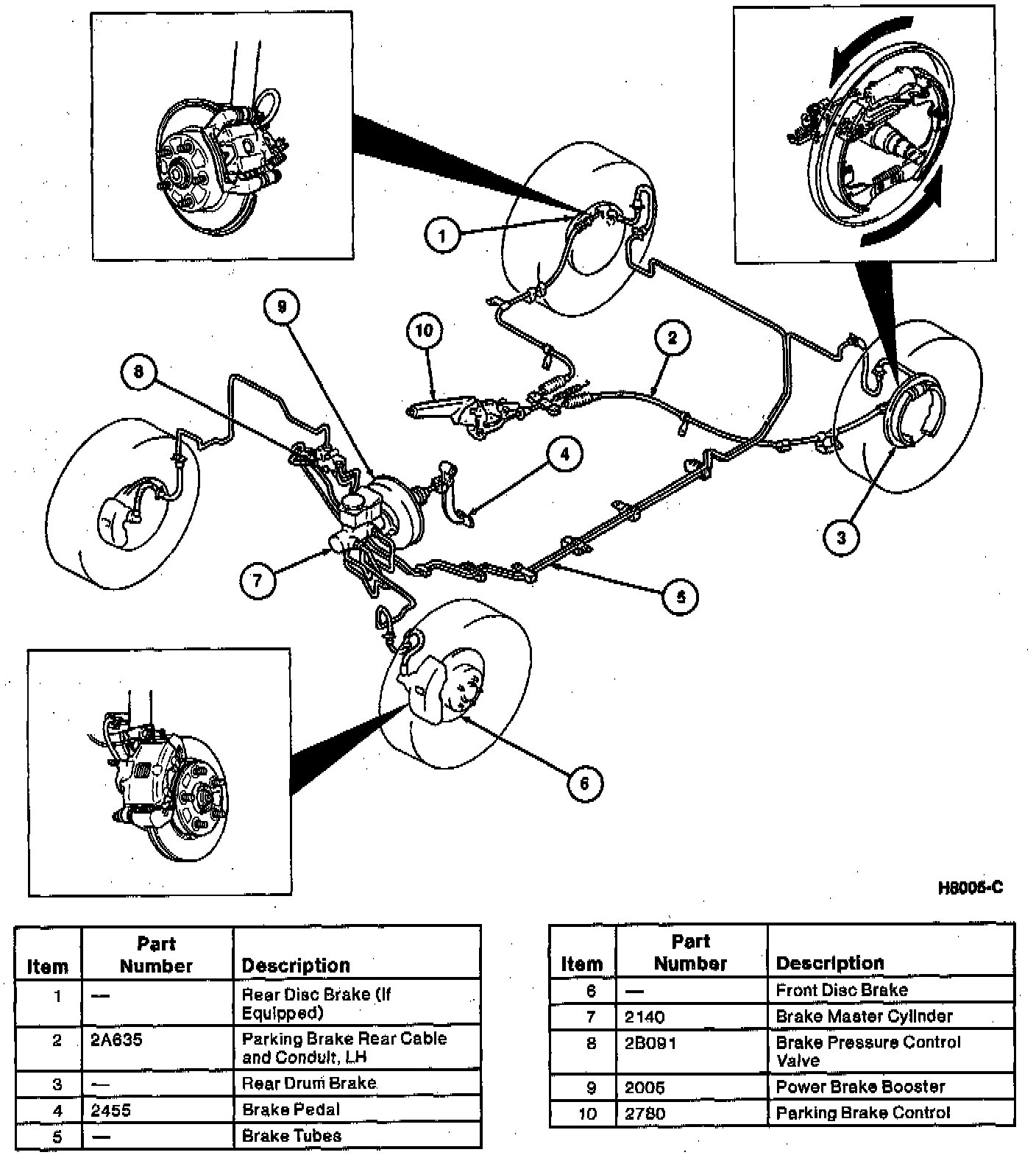
The hydraulic brake system includes:
^ Brake master cylinder
^ Brake pressure control valve
^ Brake pedal
^ Rear wheel cylinders or rear disc brake calipers
^ Front disc brake calipers
^ Brake tubes
^ Rear wheel brake hoses
^ Front brake hoses
^ Brake master cylinder fluid level sensor
The hydraulic brake system is diagonally split. The left front and right rear are on one brake circuit and the right front and left rear are on another brake circuit.
Double-walled steel tubing extends from the brake master cylinder to the rear wheel cylinders, rear disc brake calipers (if equipped) and to the front disc brake calipers. Flexible hoses make the final connection between the body-mounted brake tubes and the suspension-mounted brake assemblies.
Testing reveals that when the Anti-Lock Brake System (ABS) operates, the brake fluid pressure causes undue wear to the primary cup of the secondary piston of conventional brake master cylinders. To avoid this condition, the relief port has been abolished in brake master cylinders on-ABS-equipped vehicles and a center valve port has been provided in the secondary piston.
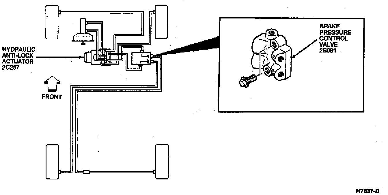
All models include a brake pressure control valve to regulate hydraulic pressure in the rear brake circuit. When the brake pedal is applied, full rear brake circuit pressure passes through the brake pressure control valve to the rear brake circuit until the valve's split point is reached. Above the split point, the brake pressure control valve begins to reduce hydraulic pressure to the rear brake circuit. This creates a balanced braking condition between the front and rear wheels, while maintaining balanced hydraulic pressure at each rear wheel.