Assembly
1. Apply thread locking compound to the piston cooling oil jet threads.Refer to tightening sequence illustration later in this procedure.
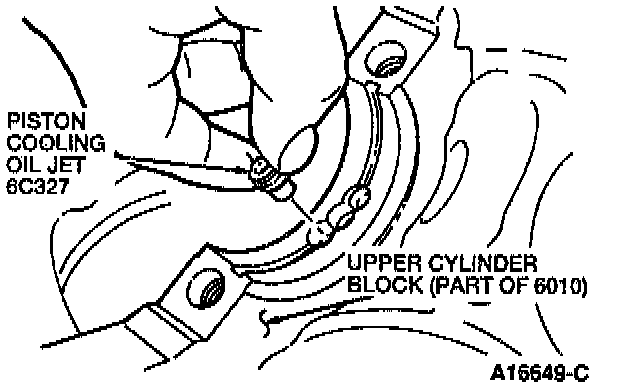
2. Use a screwdriver to install the piston cooling oil jets into the upper cylinder block. Tighten the piston cooling oil jets to 3-4 Nm (25-32 inch lbs.).
3. Remove any foreign material and oil from the contact surfaces of the upper and lower cylinder block.
4. Apply a liberal amount of clean engine oil to the crankshaft main bearings, crankshaft thrust bearings, and the main crankshaft journals.
NOTE: The No. 4 crankshaft main bearing is wider than the other crankshaft main bearings.
5. Install the upper crankshaft main bearings and upper crankshaft thrust bearings.
CAUTION: The grooved upper crankshaft main bearings are installed in the upper cylinder block.
6. Install the crankshaft in the upper cylinder block.
7. Install the lower crankshaft main bearings and lower crankshaft thrust bearings.
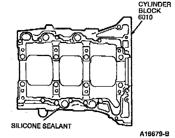
8. Apply a continuous bead of silicone sealant to the cylinder block mating surface.
NOTE: The two cylinder block halves must be secured within five minutes of applying the silicone sealant.
9. Install the lower cylinder block on the upper cylinder block.
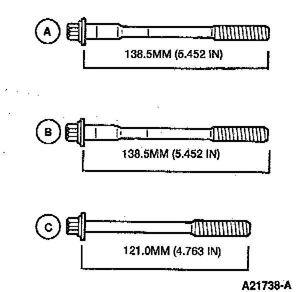
10. Measure the length of each lower cylinder block bolt before reinstalling. If the bolt length is longer than the following specifications, then replace it:
^ Cylinder block bolt A: 138.5 mm (5.452 in)
^ Cylinder block bolt B: 138.5 mm (5.452 in)
^ Cylinder block bolt C: 121.O mm (4.763 in)
Apply clean engine oil to the threads of the lower cylinder block bolts.
NOTE: The narrow part of the shank on lower cylinder block bolt B is smaller than lower cylinder block bolt A. Lower cylinder block bolts A are marked with a 4 on the head. Lower cylinder block bolts B are marked with a 1 on the head. Lower cylinder block bolts C are not marked.
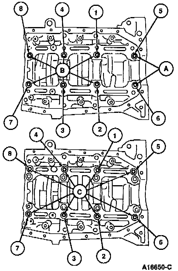
11. Tighten lower cylinder block bolts A and B in two or three steps in the order shown to 23-25 Nm (17-19 ft. lbs.). Tighten lower cylinder block bolts C in two or three steps in the order shown to 18-21 Nm (13-15 ft. lbs.).
NOTE: Lower cylinder block bolts A are marked with a 4 on the head. Lower cylinder block bolts B are marked with a 1 on the head. Lower cylinder block bolts C are not marked.
12. Paint a mark on each crankshaft main bearing cap bolt head.
13. Using the marks as a reference, tighten lower cylinder block bolts A by turning them 80 +/- 5 degrees.
14. Using the marks as a reference, tighten lower cylinder block bolts B by turning them 70 +/- 5 degrees.
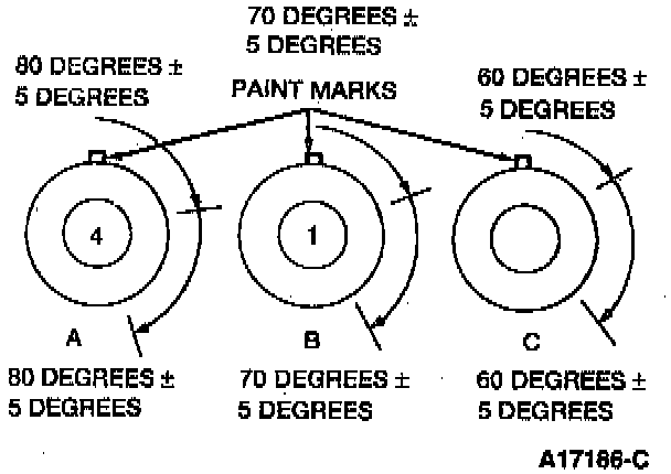
15. Using the marks as a reference, tighten lower cylinder block bolts C by turning them 60 +/- 5 degrees.
16. Further tighten each lower cylinder block bolt, an additional time, by repeating steps 13-15.
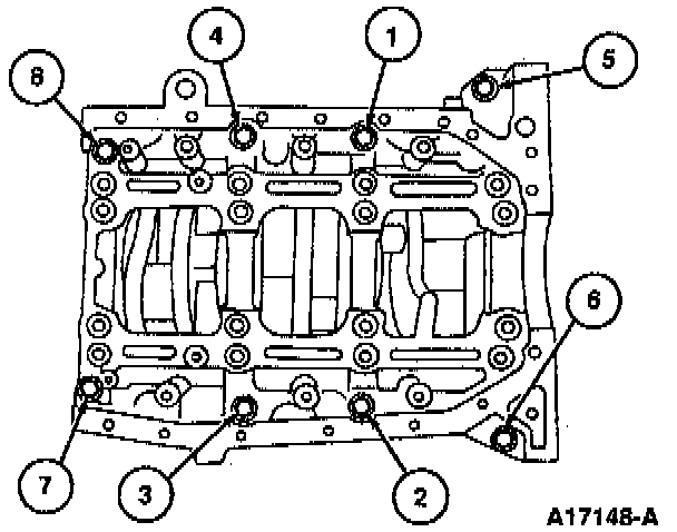
17. Tighten the lower cylinder block bolts in the order shown to 19-21 Nm (14-15 ft. lbs.).
18. Check the crankshaft end play.
19. Apply a small amount of clean engine oil to the lip of the new crankshaft rear oil seal.
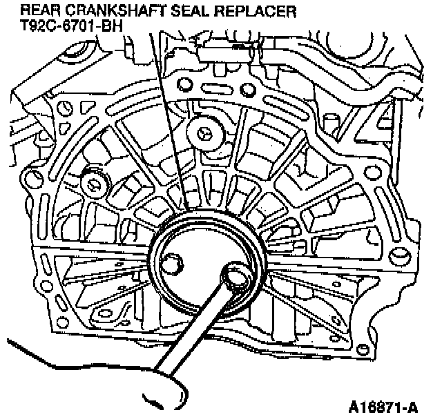
20. Use Rear Crankshaft Seal Replacer T92C-6701-BH to install the new crankshaft rear oil seal.
21. Apply a liberal amount of clean engine oil to the cylinder walls, pistons, new piston ring, crankshaft main bearings, and main crankshaft journals.
(Part 1 Of 2):
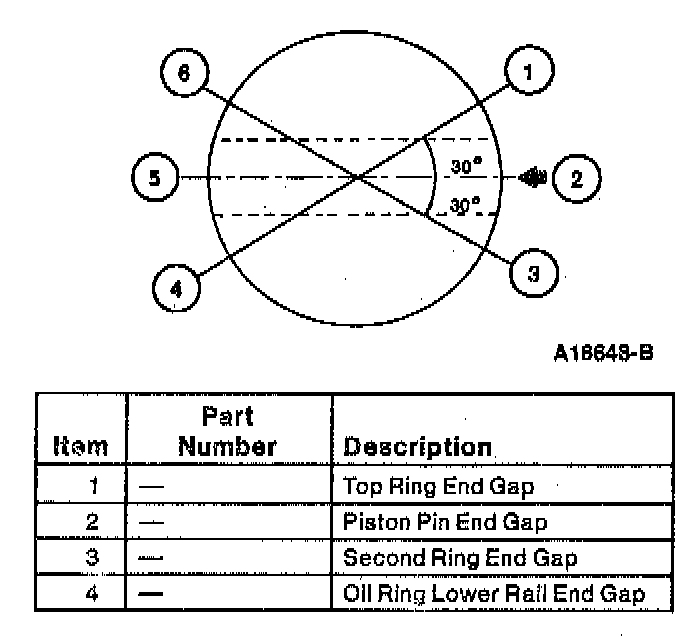
(Part 2 Of 2):
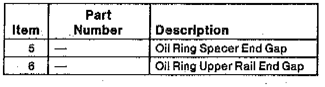
22. Check the piston rings for proper ring end gap positioning on the piston. Apply a liberal amount of clean engine oil to the piston rings and align the piston ring end gap as shown.
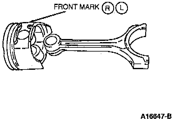
23. Use Piston Ring Compressor D81L-6002-C, or equivalent, to insert the pistons into the cylinder block.
NOTE: Install the pistons with the L mark (LH bank) and the R mark (RH bank) facing the front of the engine. Installation of the piston is easier if the crankshaft is in the bottom dead center (BDC) position. Make sure the connecting rod journal and connecting rod bearing surfaces are free of dirt and oil.
24. Install the upper connecting rod bearings into the connecting rods.
NOTE: Check the connecting rod bearing oil clearance.
25. Align the connecting rods over the crankshaft and press the piston toward the crankshaft the connecting rods are seated against the crankshaft.
26. Install the lower connecting rod bearings into the connecting rod bearing caps.
27. Install the connecting rod caps onto the connecting rods.
CAUTION: Ensure that the connecting rod caps are installed in the same direction and on the same connecting rod from which they were removed.
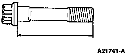
28. Measure the length of each connecting rod cap bolt before reinstalling. If the connecting rod cap bolt length is longer than 48.0 mm (1.89 inch) then replace it. Apply clean engine oil to the threads of the connecting rod cap bolts.
29. Tighten the connecting rod cap bolts to 22-27 Nm (16-19 ft. lbs.).
30. Paint a mark on each connecting rod cap bolt head.
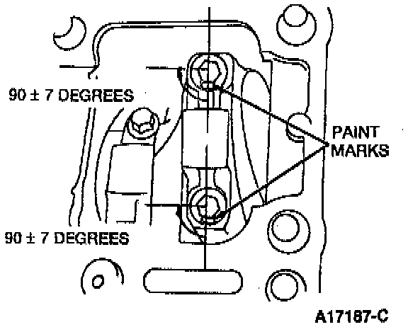
31. Use the marks as a reference and tighten the connecting rod cap bolts by turning them 90 degrees.
32. Apply clean engine oil to the oil pump housing and the new crankshaft front seal.
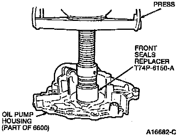
33. Use a press and Front Seals Replacer T74P-6150-A to press the new crankshaft front seal into the oil pump housing.
NOTE: Crankshaft front seal protrusion should measure 0-0.7 mm (0-0.021 inch).
34. Apply clean engine oil to the new oil pump to cylinder block ring.
35. Install a new oil pump to cylinder block ring onto the oil pump.
NOTE: Make sure the oil pump housing mating surface is free of dirt and oil.
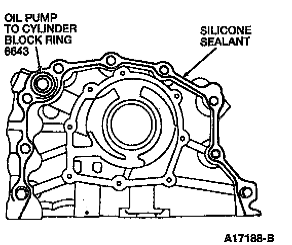
36. Apply a continuous bead of silicone sealant to the oil pump housing mating surface and install the oil pump housing.
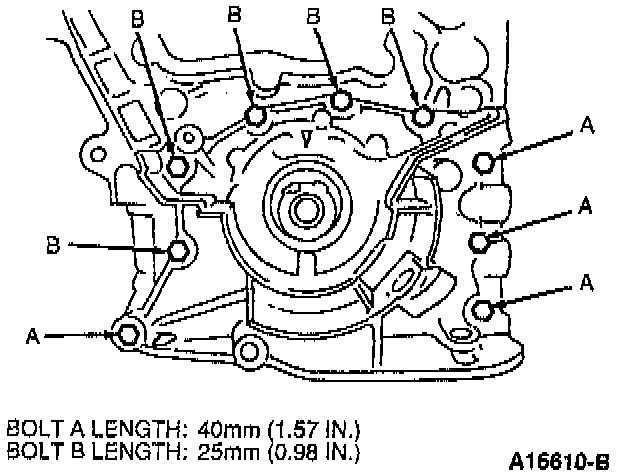
37. Tighten the oil pump bolts to 19-25 Nm (14-18 ft. lbs.).
38. Install a new water pump housing gasket and the water pump.
NOTE: Make sure the water pump mating surfaces are free of old water pump housing gasket material, dirt and oil.
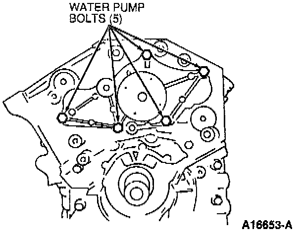
39. Tighten the water pump bolts to 19-25 Nm (14-18 ft. lbs.).
40. Install the oil pan baffle. Tighten the oil pan baffle bolts to 19-25 Nm (14-18 ft. lbs.).
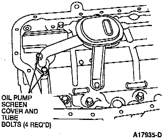
41. Install the oil pump screen cover and tube with a new gasket. Tighten the four oil pump screen cover and tube bolts to 8-10 Nm (71-88 inch lbs.).
NOTE: Tighten the oil pump screen cover and tube-to-oil pump bolts first.
42. Remove the old sealant from the threads of the oil pan bolts and the bolt holes in the cylinder block.
CAUTION: Failure to remove the old sealant from the oil pan bolts and bolt holes may cause the cylinder block to crack.
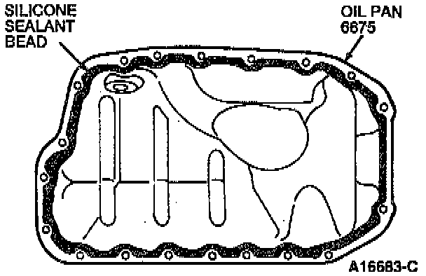
43. Apply a continuous bead of silicone sealant to the on pan, on the inside of the bolt holes.
NOTE: Be sure to install the oil pan within five minutes after applying the sealant. Make sure the oil pan mating surfaces are free of old gasket material, dirt and oil.
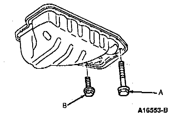
44. Install the oil pan and bolts. Tighten the oil pan bolts A to 19-25 Nm (14-18 ft. lbs.) and the oil pan bolts B to 3-10 Nm (71-88 inch lbs.).
45. Use Knock Sensor Remover T92C-12699-AH to install the Knock Sensor (KS). Tighten the KS to 20-34 Nm (14-25 ft. lbs.).
46. Install the water bypass hose and rear water hose connection with a new gasket. Tighten the rear water hose connection bolts to 19-25 Nm (14-18 ft. lbs.).
47. Secure the KS wire to the water bypass hose with the retaining clip. Install and tighten the heater water hose bracket bolt to 19-25 Nm (14-18 ft. lbs.).
48. Install the oil filter adapter with a new gasket. Tighten the oil filter adapter bolts to 19-25 Nm (14-18 ft. lbs.).
49. Connect the oil cooler hoses to the cylinder block.
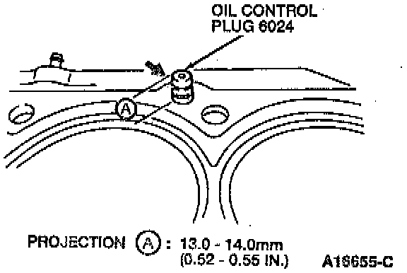
50. Measure the amount of projection of the oil control plug. The projection should measure 13-14 mm (0.52-0.55 inch).

51. Use Oil Control Plug Replacer T92C-6327-DH and Driver Handle T87P-3504-D to replace the oil control plug if the projection height is no it within specifications. Tap the new oil control plug into the cylinder head.
52. Install the new oil control plug O-rings.
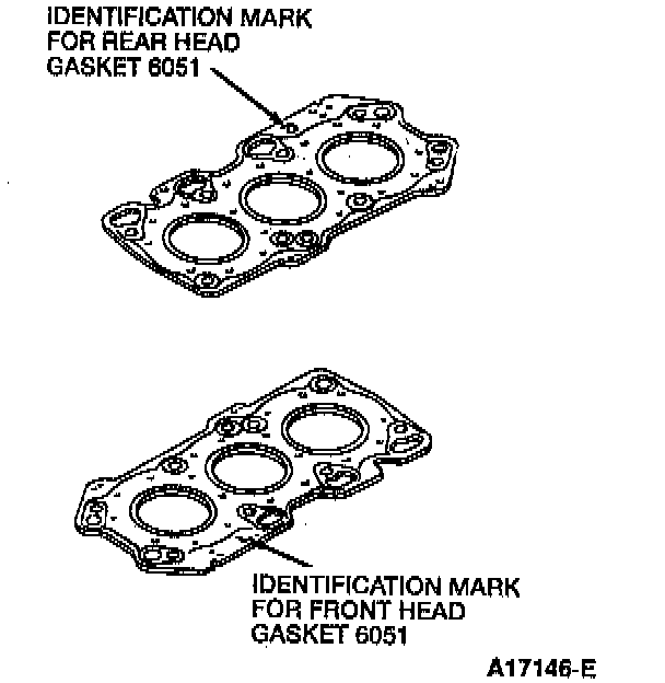
53. Install new head gaskets on the cylinder block with the identification marks facing up.
NOTE: Make sure the cylinder block and cylinder head mating surfaces are free of the old gasket material, dirt and oil. The rear head gasket and the front head gasket are not interchangeable.
54. Install the cylinder heads on the cylinder block.
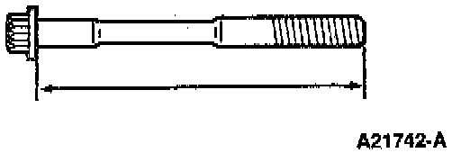
55. Measure the length of each cylinder head bolt before reinstalling. If the cylinder head bolt length is longer than 132.5 mm (5.217 inch), then replace it. Apply clean engine oil to the threads of the cylinder head bolts.
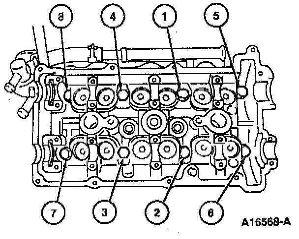
56. Tighten the cylinder head bolts in two or three steps in the sequence shown to 23-26 Nm (17-19 ft. lbs.).
57. Put a paint mark on each cylinder head bolt head.
58. Using the paint marks as a reference, tighten the cylinder head bolts by turning them 90 +/- 5 degrees.
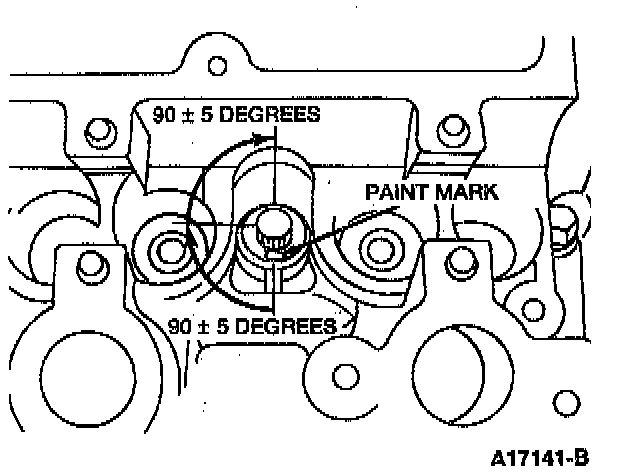
59. Tighten the bolts again by turning them an additional 90 +/- 5 decrees.
60. Connect the oil cooler hose to the oil filter adapter. Tighten the oil cooler hose bracket bolt to 19-25 Nm (14-18 ft. lbs.).
61. Apply clean oil to the HLA bores and the HLAs.
62. Install the HLAs into the bore from which they were removed and verify that they move freely in their bores.
63. Apply clean engine oil to the camshaft journals and supports.
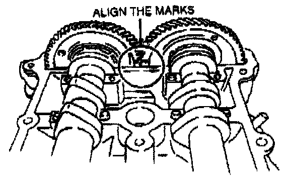
64. Install the camshafts so the marks on the camshaft sprockets are aligned.
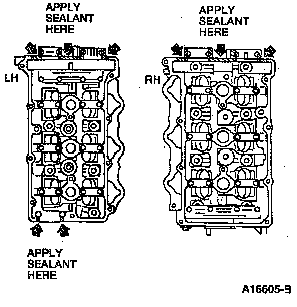
65. Apply a light coat of sealant to the areas shown.
CAUTION: Do not allow sealant to contact the camshafts.
NOTE: Make sure the front camshaft bearing end cap and the cylinder head mating surfaces are free of old gasket material, dirt and oil.
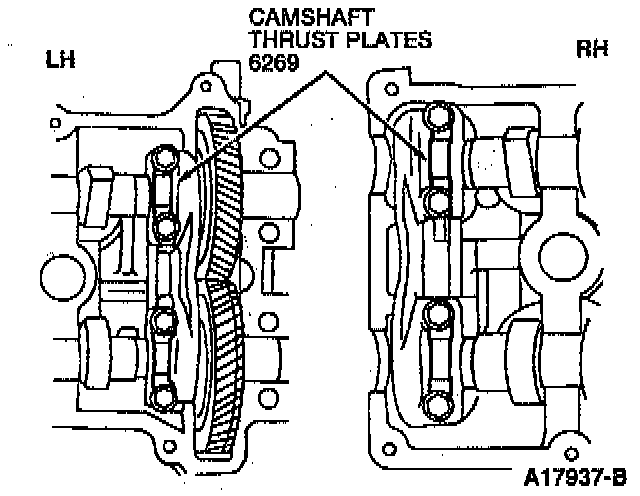
66. Install the camshaft thrust plates. Tighten the camshaft thrust plate bolts until the camshaft thrust plates are seated against the cylinder head.
67. Install the camshaft bearing caps and camshaft bearing end caps. The rear camshaft bearing caps are marked with numbers and the front camshaft bearing caps are marked with letters.
CAUTION: Do not install the camshaft bearing caps when the camshaft lobes are depressing any of the HLAs. Damage to the thrust journal support or camshaft may result.
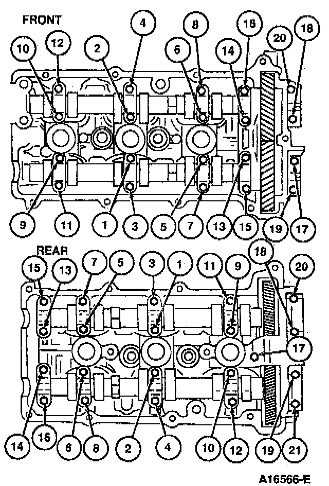
68. Tighten the camshaft bearing cap bolts, the camshaft bearing end cap bolts, and camshaft thrust plate bolts, in five or six equal steps, in the sequence shown, to 11-14 Nm (98-123 inch lbs.).
69. Apply a light coating of engine oil to the camshaft oil seal and the cylinder head.
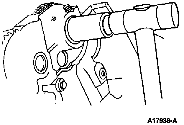
70. Use a suitable socket and a hammer to install the camshaft oil seal. Camshaft oil seal protrusion should measure 0-0.5 mm (0-0.020 inch). Repeat for each camshaft oil seal.
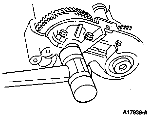
71. Apply sealant to new blind caps and tap the blind caps in using a plastic hammer.
72. Install the water inlet connection and tighten the water pump inlet connector bolts to 19-25 Nm (14-18 ft. lbs.).
73. Install the seal plate and tighten the seal plate bolts to 8-10 Nm (71-88 inch lbs.).
74. Install the rear camshaft sprocket so the timing mark is facing the front of the engine and the timing mark pin aligns with the knock pin.
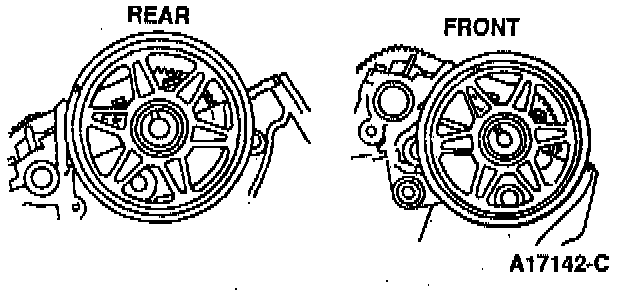
75. Install the front camshaft sprocket so the timing mark is facing the front of the engine and the timing mark pin aligns with the knock pin.

76. Install the camshaft sprockets, then the camshaft sprocket bolts. Tighten the camshaft sprocket bolts to 123-140 Nm (90-103 ft. lbs.).
NOTE: Use a suitable wrench on the camshaft cast hexagon to hold the camshafts.
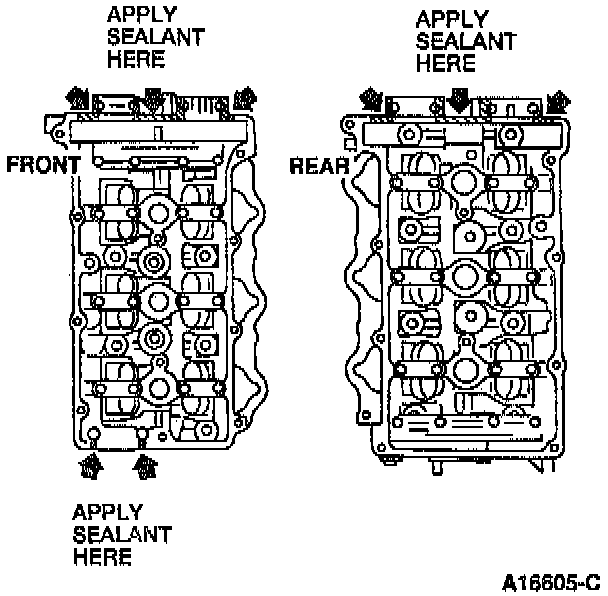
77. Apply sealant to the cylinder head as shown.
NOTE: Make sure the cylinder head mating surfaces are free of old gasket material, dirt and oil.
78. Install new valve cover gaskets.
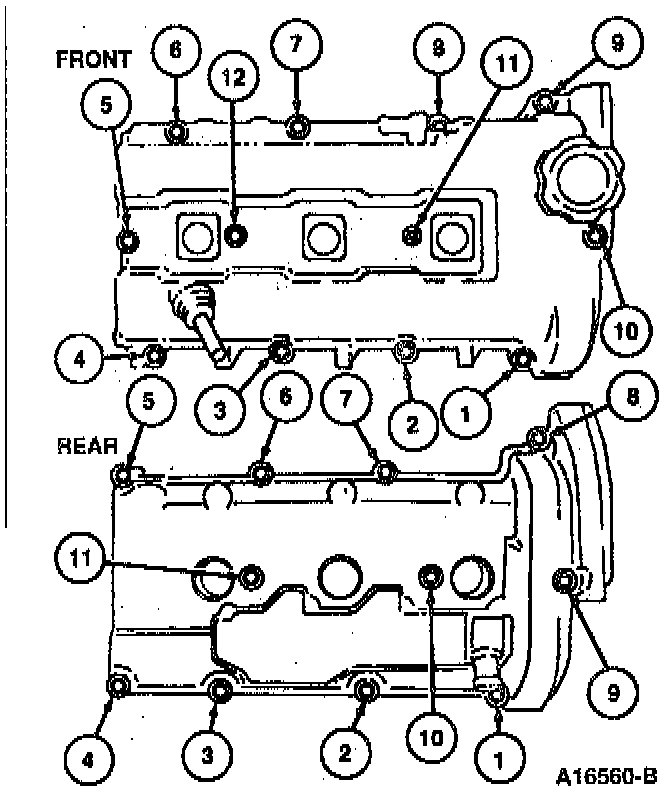
79. Install the valve covers and tighten the valve cover bolts in two steps, in the sequence shown, to 5-8 Nm (45-70 inch lbs.).
NOTE: The front valve cover bolts are round and longer.
80. Connect the crankcase ventilation tube to the front valve cover.
81. Install the fuel injection supply manifold and fuel tube bracket. Tighten the fuel tube bracket bolts to 8-10 Nm (71-88 inch lbs.).
82. Install the crankshaft sprocket key and the crankshaft pulley. Temporarily tighten the crankshaft pulley bolt.
83. Install the lower timing belt idler and tighten the lower timing belt idler bolt to 38-51 Nm (28-38 ft. lbs.).
84. Install the upper timing belt idler and tighten the upper timing belt idler bolt to 38-51 Nm (28-38 ft. lbs.).
85. Install the timing belt tensioner and tighten the timing belt tensioner bolt to 35-51 Nm (26-37 ft. lbs.).
Crankshaft Timing Marks:
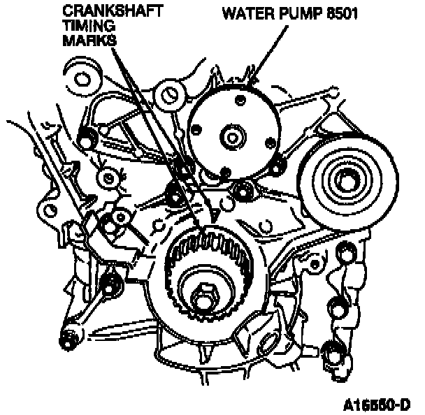
86. Turn the crankshaft sprocket in the normal direction of rotation until the crankshaft sprocket timing mark is off by one tooth as shown.
Camshaft Timing Marks:
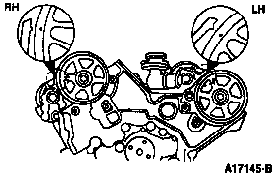
87. Align the camshaft sprockets to TDC.
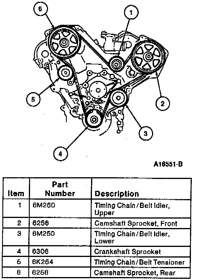
88. Install the timing belt.
89. Turn the crankshaft in the normal direction of rotation, until the crankshaft timing mark is at TDC.
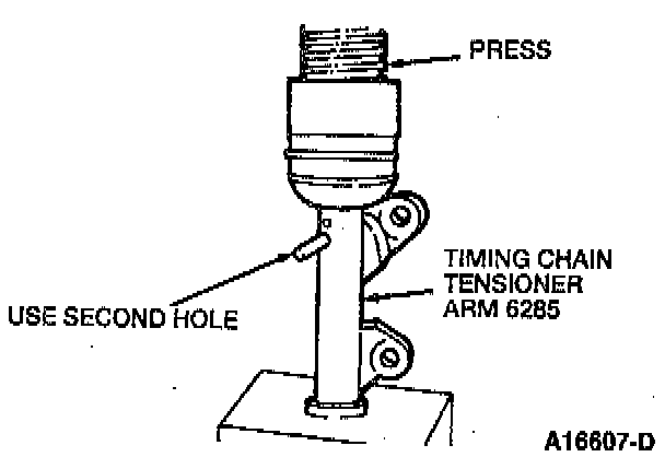
90. Compress the timing chain tensioner arm until the hole in the piston is aligned with the second hole in the case. Insert a 1.6 mm (0.06 inch) diameter wire or pin through the second hole to keep the timing belt tensioner arm compressed.
91. Install the timing belt tensioner arm and tighten the timing belt tensioner arm bolts to 19-25 Nm (14-18 ft. lbs.).
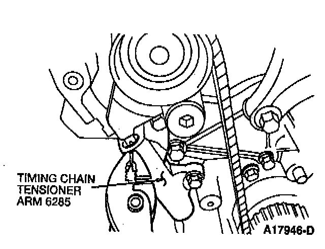
92. Remove the pin from the timing belt tensioner arm.
93. Turn the crankshaft two complete revolutions in the direction of normal rotation, to assure timing is correct.
NOTE: When correctly timed, the crankshaft timing mark will line up and will NOT be one tooth off.
94. Make sure the timing belt deflection is 6-8 mm (0.24-0.31 inch).
95. Install the RH front engine support insulator bracket and tighten the RH front engine support insulator bracket bolts to 44-60 Nm (32-44 ft. lbs.).
96. Install the rear engine front cover. Tighten the engine front cover bolts to 8-10 Nm (71-88 inch lbs.).
97. Install the crankshaft position sensor and tighten the CKP sensor bolts to 8-10 Nm (71-88 inch lbs.).
98. Install the oil level indicator tube with a new O-ring. Tighten the oil level indicator tube bolt to 8-10 Nm (71-88 inch lbs.).
99. Install the water pump pulley and tighten the water pump pulley bolts to 8-10 Nm (71-88 inch lbs.).
100. Remove the crankshaft pulley hub bolt.
101. Clean the crankshaft pulley bolt threads and apply clean engine oil to the threads.
CAUTION: Do not damage the crankshaft position (CKP) sensor when installing the crankshaft pulley.
102. Use Crankshaft Pulley Holder T92C-6316-AH to install the crankshaft pulley and tighten the crankshaft pulley bolt to 157-166 Nm (116-122 ft. lbs.).
103. Apply a small amount of clean engine oil to the new oil filter gasket.
104. Install the oil filter by hand until the oil filter gasket contacts the sealing surface, then turn an additional 1 and 1/6 turn.
105. Install the ignition wire separators.
106. Install the spark plugs and tighten to 15-22 Nm (11-16 ft. lbs.).
107. Install the A/C compressor mounting bracket if equipped, and tighten the A/C compressor mounting bracket bolts to 38-51 Nm (28-38 ft. lbs.).
108. Install the front engine lifting eye and tighten the front engine lifting eye bolts to 19-25 Nm (14-18 ft. lbs.).
109. Install the rear engine lifting eye and tighten the rear engine lifting eye bolt to 38-51 Nm (28-38 ft. lbs.).
110. Install new intake manifold gaskets and the intake manifold. Tighten the five intake manifold bolts and two nuts to 19-25 Nm (14-18 ft. lbs.).
111. Apply clean engine oil to the distributor drive blade and the new distributor cap gasket. Place the new distributor cap gasket on the distributor.
112. Align the groove of the distributor body and shaft gear mark.
113. Install the distributor and tighten the distributor bolts to 19-25 Nm (14-18 ft. lbs.).
114. Connect the distributor to spark plug wires.
115. Install the front exhaust manifold and a new exhaust manifold gasket. Tighten the front exhaust manifold bolts to 19-25 Nm (14-18 ft. lbs.)
116. Install the front exhaust manifold shield and tighten the front exhaust manifold shield bolts to 8-10 Nm (71-88 inch lbs.).
117. Install the rear exhaust manifold and a new exhaust manifold gasket. Tighten the rear exhaust manifold bolts to 19-25 Nm (14-18 ft. lbs.).
118. Install the rear exhaust manifold shield and tighten the rear exhaust manifold shield bolts to 8-10 Nm (71-88 inch lbs.).
119. Install the A/C and generator belt idler bracket and tighten the A/C and generator belt idler bracket bolts to 19-25 Nm (14-18 ft. lbs.).
NOTE: Tighten the upper A/C and generator belt idler bracket bolt, then the lower A/C and generator belt idler bracket bolt.
120. Install the generator and tighten the generator bolts to 38-51 Nm (28-38 ft. lbs.). Tighten the generator to generator adjusting arm bolts to 19-25 Nm (14-18 ft. lbs.).