Disassembly
1. Before starting disassembly, remove any accessories and emission control equipment which are not directly attached to the engine and drain any remaining engine oil into a suitable container.
2. If equipped, remove the A/C compressor mounting bracket.
3. Remove the two generator bolts and remove the generator (GEN).
4. Remove the A/C and generator drive belt idler bracket.
5. Remove the exhaust manifolds.
6. Remove the ignition wire separators.
7. Remove the two distributor bolts. Remove the distributor and the distributor to spark plug wires.
8. Remove the intake manifold.
9. Remove the bolt from each engine lifting eye, and then remove the front engine lifting eye and rear engine lifting eye.
10. Remove the spark plugs.
11. Use an oil filter wrench to remove the oil filter.
NOTE: Make sure the oil filter gasket is removed with the oil filter.

12. Use Crankshaft Pulley Holder T92C-6316-AH to hold the crankshaft pulley and remove the crankshaft pulley bolt.
13. Remove the crankshaft pulley.

14. Use Water Pump Pulley Tool T92C-6312-AH to remove the four water pump pulley bolts. Remove the water pump pulley.
15. Remove the oil level dipstick.
16. Remove the oil level indicator tube bolt and then pull the oil level indicator tube from the engine.
17. Remove the crankshaft position (CKP) sensor bolt. Remove the (CKP) sensor.
18. Remove the rear engine front cover bolts.
19. Remove the front engine front cover bolts. Remove the engine front covers.
20. Remove the RH engine support insulator bracket bolts and the RH engine support insulator bracket.
Belt Tensioner Bolt Removal:

21. Remove the two timing chain tensioner arm bolts in the sequence shown. Remove the timing chain tensioner arm.
NOTE: Remove the lower timing chain tensioner arm bolt before the upper timing chain tensioner arm bolt.

22. Mark the direction of rotation on the timing belt for proper installation.
23. Remove the timing belt.
24. Remove the timing belt tensioner bolt. Remove the timing belt tensioner.
25. Remove the lower timing belt idler bolt and then remove the lower timing belt idler.
26. Remove the upper timing belt idler bolt and then remove the upper timing belt idler.

27. Use Crankshaft Damper Remover T74P-6316-A to remove the crankshaft sprocket.
28. Remove the crankshaft sprocket key.
29. Disconnect the crankcase ventilation tube from the front valve cover.
30. Remove the front and rear valve cover bolts and the front valve cover and rear valve cover.

31. Remove the camshaft sprocket bolts then the camshaft sprockets.
NOTE: Use a suitable wrench on the camshaft cast hexagon to hold the camshaft.
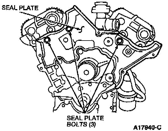
32. Remove the three seal plate bolts and the seal plate.

33. Remove the four front water hose connection bolts and the front water hose connection.

34. Align the camshaft knock pins, as shown, to release the pressure from the HLAs.
CAUTION: Do not remove the camshaft bearing caps when the camshaft lobes are pressing on the hydraulic lash adjusters (HLA). Doing so may cause damage to the camshaft and/or the thrust journal support of the cylinder head.

35. Loosen the camshaft bearing end cap bolts in five or six steps, in the sequence shown and remove the camshaft bearing end caps.
36. Remove the blind caps.

37. Loosen the camshaft thrust plate bolts and camshaft bearing cap bolts in five or six steps, in the sequence shown.
38. Remove the camshaft bearing caps and the camshaft thrust plates.
39. Remove the camshafts.
40. Remove the camshaft oil seals. Discard the camshaft oil seals.
CAUTION: Place HLAs aside and identify them for installation. If an HLA is to be reused, store it upside down in an oil filled container. Installing the HLAs in the wrong bore may cause faulty HLA operation.
41. Loosen the HLAs from the cylinder heads and store them upside down in an oil-filled container.
42. Remove the fuel tube bracket.
Fig. 10, Cylinder Head Bolt Removal:

43. Loosen the cylinder head bolts in two or three steps in the sequence shown, and remove the cylinder head bolts.
44. Remove the cylinder heads and head gaskets from the cylinder block.
45. Remove the oil cooler outlet tube and hoses from the cylinder block.
46. Remove the oil filter adapter bolts. Remove the oil filter adapter from the cylinder block.
47. Disconnect the clip and separate the KS wiring from the water bypass hose.
48. Remove the heater water hose bracket bolt.
49. Remove the water bypass tube and the rear water hose connection as an assembly with the gasket.
NOTE: Make sure the gasket is removed with the rear water hose connection.
50. Use Knock Sensor Remover T92C- 12699-AH to remove the KS.
51. Remove the nineteen oil pan bolts and remove the sealant from the oil pan bolt threads.
52. Carefully pry the oil pan from the cylinder block.
53. Remove the four oil pump screen cover and tube bolts and the oil pump screen cover and tube.
54. Remove the six oil pan baffle bolts and the oil pan baffle.
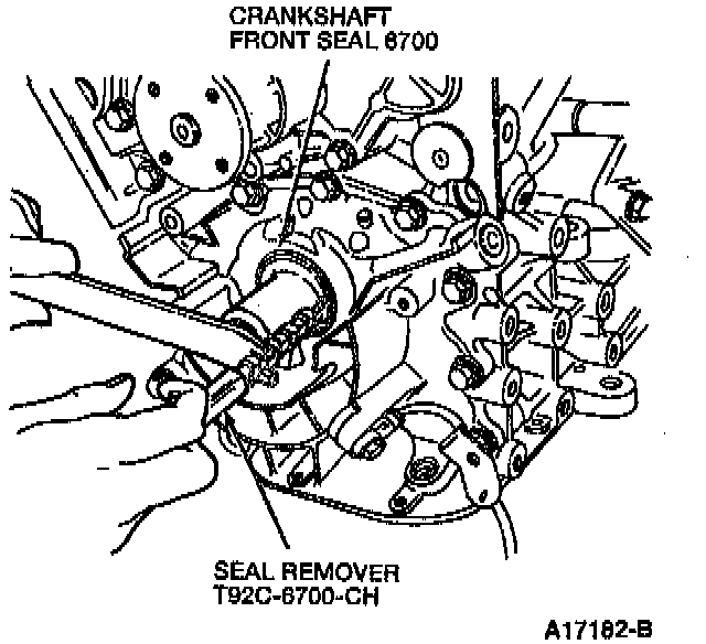
55. Use Seal Remover T92C-6700-CH to remove the crankshaft front seal.
56. Remove the five water pump bolts and the water pump. Discard the water pump housing gasket.
57. Remove the two generator adjusting arm-to-cylinder head bolts. Remove the generator adjusting arm.
58. Remove the oil pump bolts and the oil pump. Discard the oil pump to cylinder block ring.
59. Remove two bolts from one connecting rod cap.
CAUTION: Identify and position the connecting rod caps in order of removal to ensure proper placement when installing.
60. Remove the connecting rod cap from the connecting rod.
61. If necessary, use Cylinder Ridge Reamer T64L-6011-EA to remove the upper cylinder bore ridge.

62. Remove the piston and connecting rod assembly through the top of the cylinder block by pushing on the bottom of the piston with a wooden handle.
63. Install the connecting rod cap onto the connecting rod. Repeat steps 61-64 for the remaining pistons.

64. Use Seal Remover T92C-6700-CH to remove the crankshaft rear oil seal.
65. Check the crankshaft end play.

66. Loosen the lower cylinder block bolts in two steps, in the sequence shown. Remove the lower cylinder block bolts.

67. Pry the cylinder block halves apart at the points shown.
68. Remove the two lower crankshaft thrust bearings and all of the lower crankshaft main bearings.
NOTE: If the lower crankshaft main bearings are to be reused, they should be identified to assure that they are installed in their original positions.
69. Remove the crankshaft from the cylinder block.
70. Remove the two upper crankshaft thrust bearings and all of the upper crankshaft main bearings from the cylinder block.
NOTE: If the upper crankshaft thrust bearings and the upper crankshaft main bearings are to be reused, they should be identified to assure that they are installed in their original positions.
71. Use a screwdriver to remove the piston cooling oil jets from the upper cylinder block.