Starting System: Description and Operation
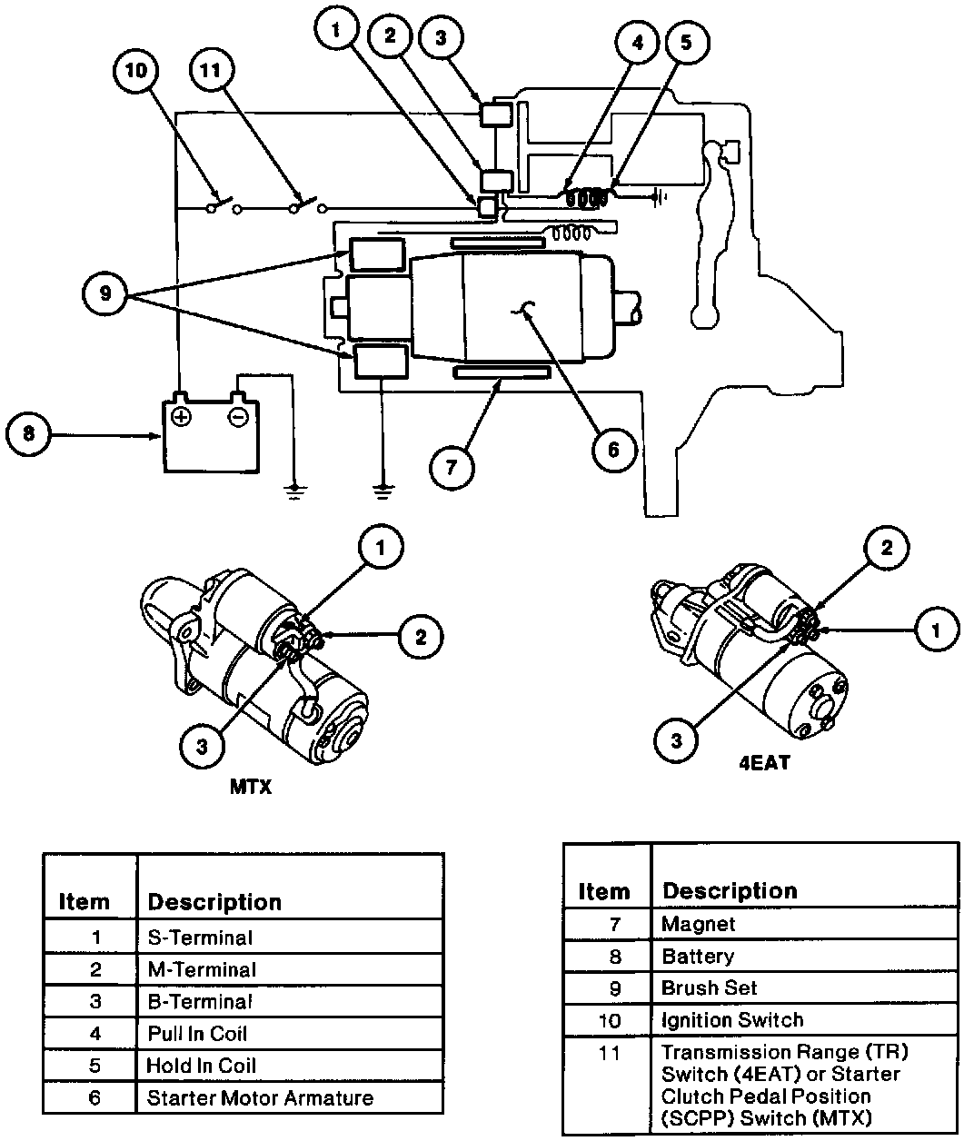
STARTER SYSTEMThe function of the starting system is to crank the engine at a speed fast enough to permit the engine to start. The starting system consists of:
^ Starter motor and starter solenoid
^ Battery
^ Ignition switch
^ Transmission range (TR) switch (4EAT)
^ Starter clutch pedal position (SCPP) switch (MTX)
NOTE: Engine oil viscosity can also affect engine cranking speed.
The starting circuit uses heavy duty cables to handle the high current used to crank the engine. The resistance in the starting circuit must be kept to a minimum, allowing enough current for adequate starter motor operation. Loose or corroded connections or partially broken wires will result in slow cranking speeds and may prevent the starter motor from cranking the engine.
If the starter motor or circuit is suspected to be the cause of a no-start condition, use the Symptom Chart and diagnostic tests, to isolate the condition.
The starting system has two electrical circuits, a low and a high-current circuit.
The low-current circuit is the solenoid control circuit, consisting of:
^ Ignition switch
^ Starter solenoid
^ TR switch (4EAT)
^ SCPP switch (MTX)
The high-current circuit connects the starter motor to the battery positive (+) terminal. This circuit uses heavy duty cable because of the high-current flow needed to operate the starter motor properly.
Sequence of Operation
The starter motor low-current circuit is controlled by the ignition switch. When the ignition switch is in the START position battery voltage at the S-terminal of the starter motor flows through the pull-in coil to ground. Energizing the pull-in coil produces a magnetic field which pulls the starter drive into engagement with the flywheel ring gear and contact disc into the closed position, creating a contact between the starter B-terminal and the M-terminal. The high-current circuit is then closed and full battery voltage is applied to the brush set within the starter motor, causing starter motor rotation.
The starter motor armature is connected to the starter drive. As the starter motor armature moves forward from the magnetic field of the pull-in coil, the starter drive is moved toward the flywheel. At the end of its travel, the starter drive engages with the flywheel . Once the starter drive and flywheel are fully engaged, the contact disc completes the circuit between the B-terminal, and the M-terminal and the starter motor armature rotates, which in turn rotates the flywheel and crankshaft. A hold-in coil is energized by the S-terminal, to supply the additional magnetic force required to keep the contact disc engaged as the starter motor draws current and the system voltage drops. The starter drive remains engaged until the ignition switch is released from the START position. An overrunning clutch in the starter drive protects the starter motor from excessive speeds during the brief period before the driver releases the ignition switch from the START position as the engine starts.