Removal
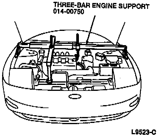
1. Use the Three-Bar Engine Support 014-00750 or equivalent to support the engine.
2. Raise and support the vehicle.
3. Remove the front wheels.
4. Remove the cotter pin and tie rod end nut.
NOTE: If the tie rod end does not separate easily, give the front wheel knuckle a sharp blow with a brass hammer to shock the taper.
Tie Rod End Remover Tool:

5. Use Tie Rod End Remover TOOL-3290-D or equivalent to separate the tie rod end from the front wheel knuckle.
6. Remove the front splash shields from the vehicle.
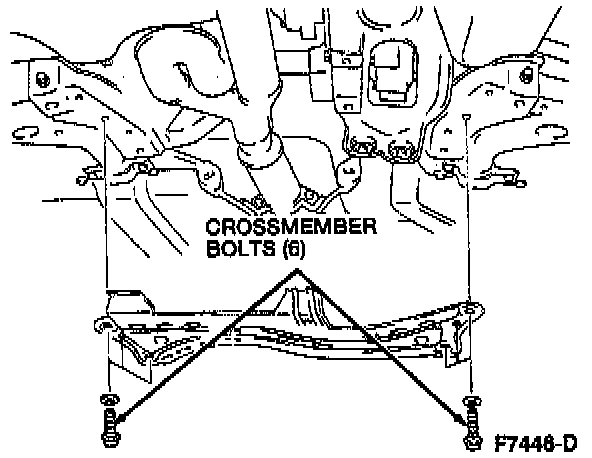
7. Remove the six crossmember bolts and remove the crossmember.
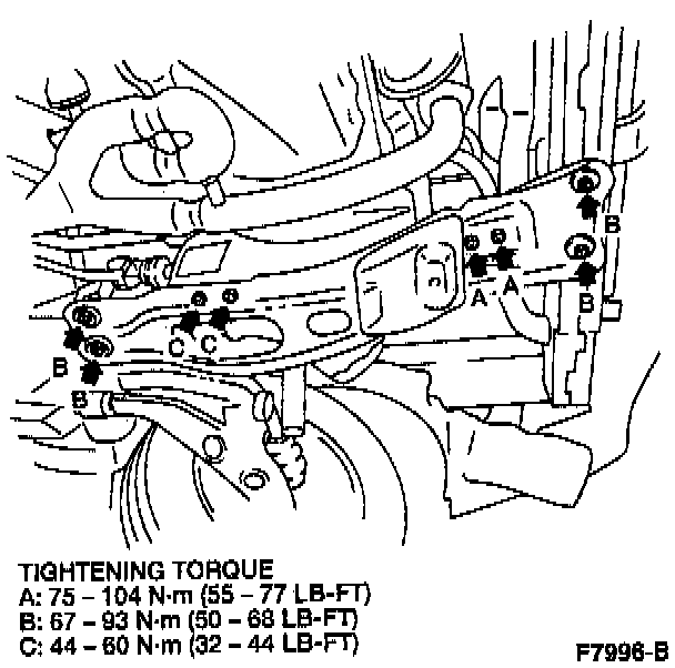
8. Remove the two transmission support crossmember bolts and six rear engine support nuts from the transmission support crossmember. Remove the transmission support crossmember.
9. Disconnect the two heated oxygen sensor (HO2S) electrical connectors.
10. Remove the exhaust inlet pipes from the exhaust manifolds and move aside. See Exhaust System.
11. Disconnect the power steering pressure hose from the steering gear and plug the power steering pressure hose.
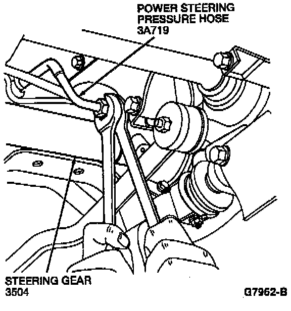
12. Disconnect the power steering return hose from the steering gear and plug the power steering return hose.
13. Remove the steering shaft U-joint shield bolt.
14. Remove the steering shaft U-joint shield.
15. Remove the ground wire bracket from the rear transaxle support bracket, 4EAT and MTX models only.
16. Remove the three rear transaxle support bracket bolts, 4EAT and MTX models only.
17. Remove the rear transaxle support insulator through bolt, 4EAT and MTX models only.
18. Remove the rear transaxle support bracket, 4EAT and MTX models only.
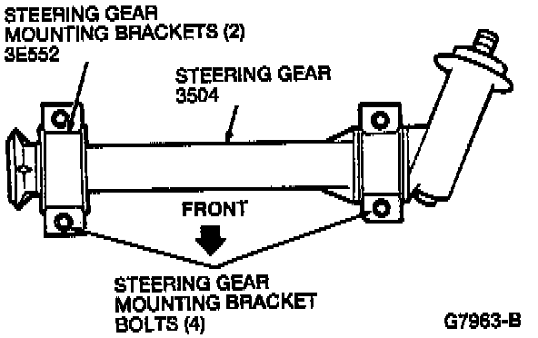
19. Remove the four steering gear mounting bracket bolts from the two steering gear mounting brackets and remove the steering gear mounting brackets.
20. Remove the steering column lower yoke-to-power steering gear input shaft and control bolt.
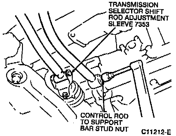
21. On MTX models, remove the control rod to support bar stud nut.
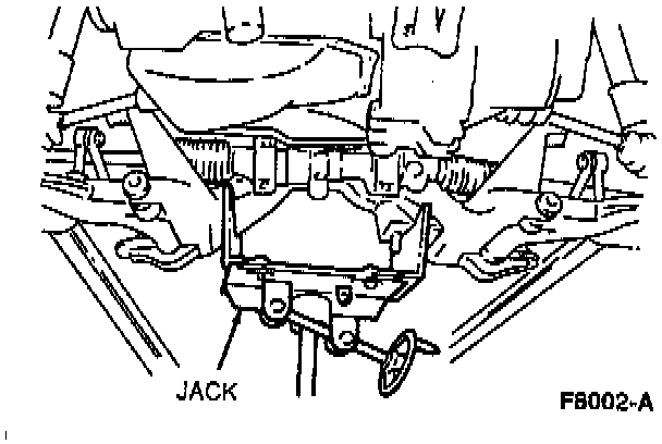
22. Position a jack under the front sub-frame.
23. Remove the six front sub-frame bolts and the two front sub-frame nuts.
24. Remove the vent attached to the driver's side of the front sub-frame.
25. Remove the upper stabilizer bar link nuts.
26. Lower the front sub-frame to allow for the removal of the steering gear.
27. Remove the steering gear from the driver's side of the vehicle.
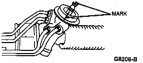
28. If the same steering gear is to be installed, make alignment marks on the power steering gear input shaft and control and the steering gear housing.