Front
REMOVAL
1. Raise and support the vehicle.
2. Remove the front wheels.
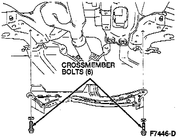
3. Remove the six crossmember bolts and remove the crossmember.
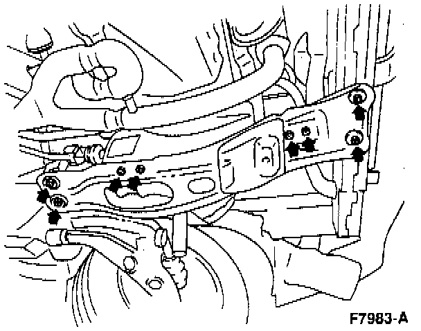
4. Remove the two rear engine support bolts and six rear engine support nuts and remove the transmission support crossmember.
5. Disconnect the heated oxygen sensor (H02S) electrical connector(s).
6. Remove the exhaust inlet pipe from the exhaust manifold and position aside. See Exhaust System.
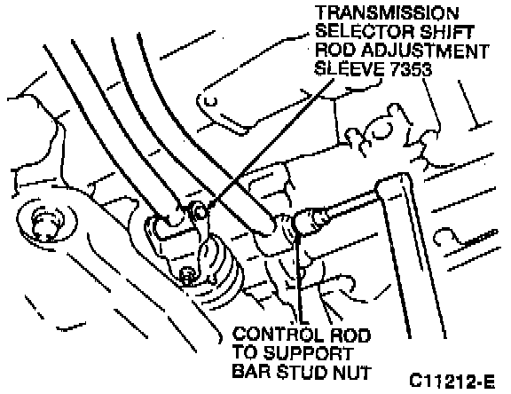
7. If equipped with a manual transaxle, remove the control rod to support bar stud nut.
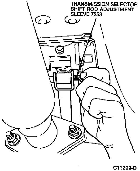
8. If equipped with a manual transaxle, remove the transmission selector shift rod adjustment sleeve nut and the transmission selector shift rod adjustment sleeve.
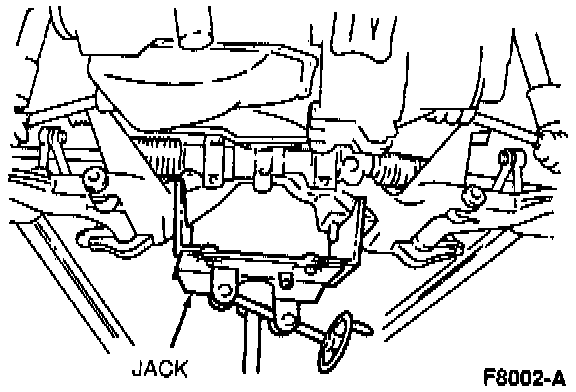
9. Position a jack under the front sub-frame.
10. Remove the four front sub-frame bolts and two front sub-frame nuts.
11. Remove the two upper stabilizer bar link nuts.
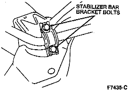
12. Remove the four stabilizer bar bracket bolts.
13. Lower the front sub-frame to allow for the removal of the front stabilizer bar.
14. Remove the front stabilizer bar from the right side of the vehicle.
INSTALLATION
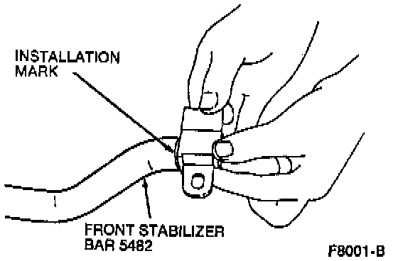
NOTE: Apply rubber grease to the inside surface of the lower suspension arm stabilizer bar insulator. Align the lower suspension arm stabilizer bar insulator with the installation mark on the front stabilizer bar.
To install, reverse the removal procedure noting the following:
^ Tighten the stabilizer bar bracket bolts to 36-54 Nm (27-40 ft. lbs.).
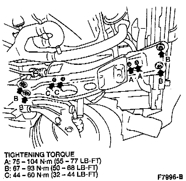
^ Tighten the rear engine support nuts and the rear engine support bolts as shown.