Assembly
CAUTION: If the clutch plates or the 2-4 band are replaced, soak the new parts in the specified automatic transmission fluid (ATF) for at least two hours before assembly. Apply the specified ATF to all seal rings, rotating parts, O-rings and sliding parts.1. Remove any remaining locking compound from the torque converter stator support bolt holes.
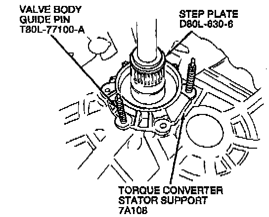
2. Use Valve Body Guide Pins T80L-77100-A to align the torque converter stator support, then use Step Plate Adapter D80L-630-6 (part of D80L-630-A) or equivalent to press the torque converter stator support into the converter case.
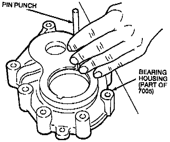
3. Remove the bearing outer race and output shaft bearing selective shim from the bearing housing.
4. Place the output gear into the converter housing.
5. Place the bearing outer race over the idler and output gear bearing.
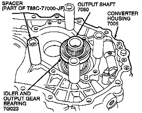
6. Place four Spacers (Part of T88C-77000-JF) on the converter housing at the positions shown.
NOTE: Whenever the Transaxle is disassembled, the bearing preload must be adjusted. The output gear and differential bearing pre load are adjusted by selecting differential bearing shims to insert under the differential bearing cups and the bearing outer race. To determine the correct thickness differential bearing shim, use Shim Selection Set T88C-77000-C along with the following procedure.
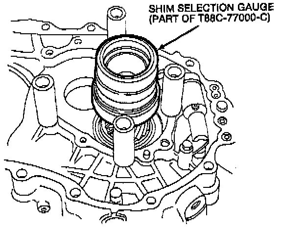
7. Place Shim Selection Gauge (part of T88C-77000-C) on the output gear. Turn the two halves of the gauge to eliminate any gap between them.
8. Place the bearing housing on the spacers, then install four Bolts (part of T88C-77000-C) with washers. Tighten to 26-30 Nm (19-22 ft. lbs.).
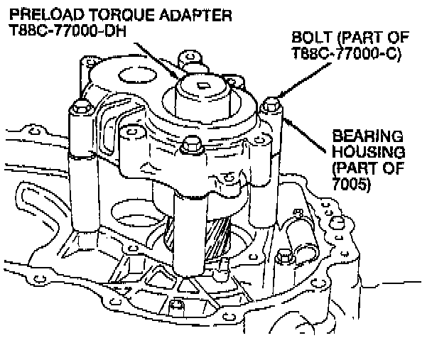
9. Place Pre load Torque Adapter T88C-77000-DH on the output gear.
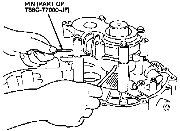
10. Using Pins (part of T88C-77000-JF) loosen the gauge halves until all of the free play is removed and the idler and output gear bearing cup is seated. Then thread the gauge halves back together.
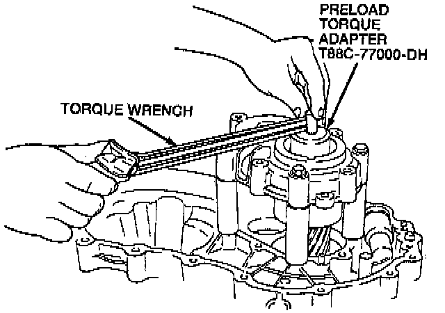
11. Attach a torque wrench to the Pre load Torque Adapter T88C-77000-DH. Measure the drag on the idler and output gear bearing.
NOTE: Read the pre load when the output gear starts to turn.
12. Turn the gauge using Pins (part of T88C-77000-JF) until a reading of 1.1-1.9 Nm (10-17 inch lbs.) is obtained on the torque wrench.
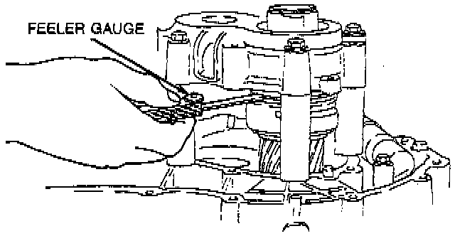
13. Use a feeler gauge to measure the gap between the two halves of the gauge. Measure the gap in four spots, at 90° intervals. Use the largest measurement.
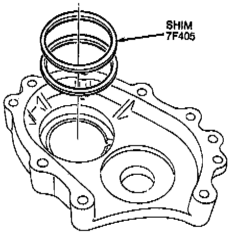
14. Select the output shaft bearing selective shims that are closest (or slightly larger) to the measured value of the gauge gap.
NOTE: Use no more than seven output shaft bearing selective shims. Select from one of the following output gear bearing selective shim kits:
^ F32Z-7F405-A includes output shaft bearing selective shims between 0.350-0.675 mm (0.0137-0.0265 inch) in increments of 0.050 mm (0.001 9 inch).
^ F32Z-7F405-B includes output shaft bearing selective shims between 0.700-1.025 mm (0.0275-0.0403 inch) in increments of 0.050 mm (0.0019 inch).
^ F32Z-7F405-C includes output shaft bearing selective shims between 1.050-1.400 mm (0.0413-0.0551 inch) in increments of 0.060 mm (0.0019 inch).
15. Remove the screws, washers, bearing housing, gauge, and bearing outer race.
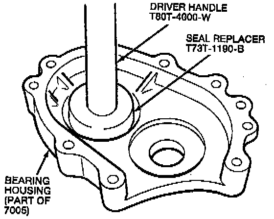
16. Use Seal Replacer T73T-1190-B and Driver Handle T80T-4000-W to press the selected output shaft bearing selective shim and bearing outer race into the bearing housing.
17. Install the bearing housing. Tighten the bearing housing bolts to 28-34 Nm (21-25 ft. lbs.).
18. Measure the bearing pre load with a pound-inch torque wrench. The preload should be 1.1-1.9 Nm (10-17 inch lbs.). Repeat the gauging process if the pre load measurement is not within specification.
19. When the proper preload specification has been obtained, remove the bearing housing.
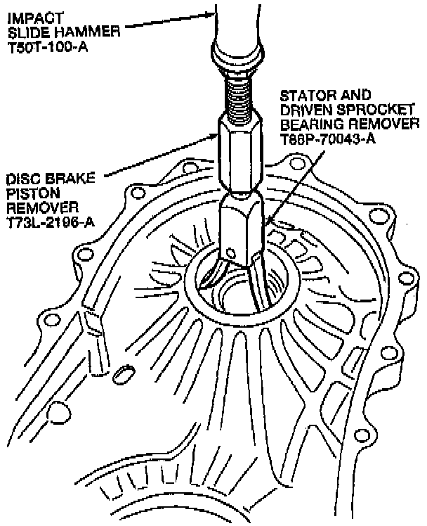
20. Use Stator and Driven Sprocket Bearing Remover T86P-70043-A, Disc Brake Piston Remover T73L-2196-A, and Impact Slide Hammer T50T-100-A to remove the rear differential bearing cup and output gear bearing selective shims from the Transaxle case.
NOTE: The following procedure explains shim selection for the differential.
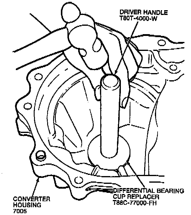
21. Use Driver Handle T80T-4000-W and Differential Bearing Cup Replace T88C-77000-FH to install the front differential bearing cup into the converter housing.
22. Place the differential into the converter housing.
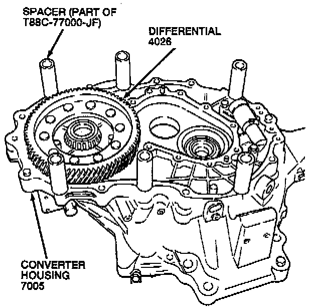
23. Place six Spacers (Part of T88C-77000-JF) on the converter housing at the positions shown.
24. Place the rear differential bearing cup over the differential bearing.
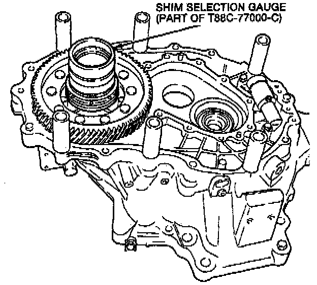
25. Place Shim Selection Gauge (part of T88C-77000-C) on the output gear. Turn the two halves of the gauge to eliminate any gap between them.
26. Place the Transaxle case on the spacers, then install six Bolts (part of T88C-77000-C) with washers. Tighten to 38-51 Nm (28-38 ft. lbs.).
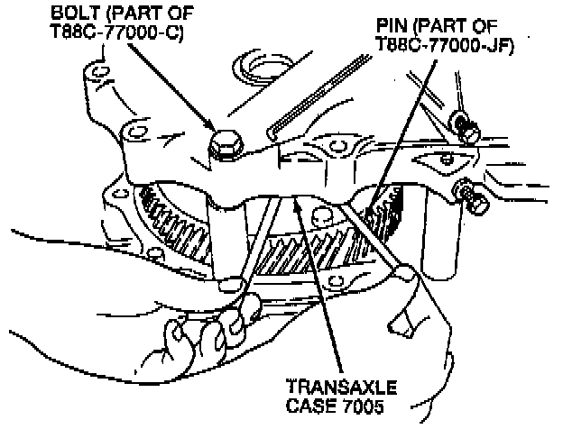
27. Using Pins (part of T88C-77000-JF) unthread the gauge halves until all the free play is removed and the differential bearing cup is seated. Then thread the gauge halves back together.
28. Engage Differential Rotator T88C-77000-L and attach a torque wrench to the adapter. Measure the drag on the differential bearing.
NOTE: Read the pre load when the differential starts to turn.
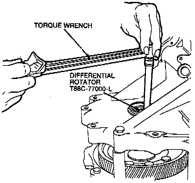
29. Measure the pre load. The pre load should be 0.49 Nm (4.3 inch lbs.).
30. Turn the gauge using Pins (part of T88C-77000-JF) until a reading of 0.5 Nm (4.3 inch lbs.) is obtained on the torque wrench.
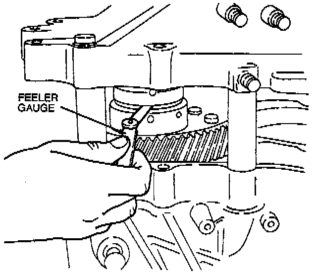
31. Use a feeler gauge to measure the gap between the two halves of the gauge. Measure the gap in four spots, at 90° intervals. Use the largest measurement.
32. Add 0.3 mm (0.012 inch) to the largest measurement. Using the chart, select the differential bearing shim closest (or slightly larger) to this final value.
NOTE: Use no more than three differential bearing shims.
Shim Thickness: Part Number
0.10 mm (0.004 inch): E92Z-4067-A
0.12 mm (0.005 inch): E92Z-4067-B
0.14 mm (0.006 inch): E92Z-4067-C
0.16 mm (0.0063 inch): E92Z-4067-D
0.18 mm (0.007 inch): E92Z-4067-E
0.20 mm (0.008 inch): E92Z-4067-F
0.50 mm (0.020 inch): E92Z-4067-N
1.00 mm (0.040 inch): E92Z-4067-Y
33. Remove the screws, washers, Transaxle case, gauge, and differential bearing cup.
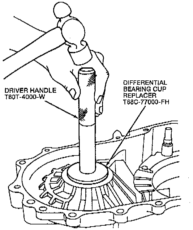
34. Use Driver Handle T80T-4000-W and Differential Bearing Cup Replacer T88C-77000-FH to install the differential bearing shim and differential bearing cup in the Transaxle case.
35. Install the Transaxle case. Tighten the Transaxle case bolts to 38-51 Nm (28-38 ft. lbs.).
36. Measure the bearing pre load with a torque wrench. The pre load should be 3.0-3.9 Nm (27-34 inch lbs.). Repeat the gauging process if the pre load measurement is not within specification.
37. When the proper pre load specification has been obtained, remove the Transaxle case.
38. Mount the converter housing to the Bench Mounted Holding Fixture T57L-500-B.
39. Install new torque converter stator support bolts. Tighten the eight torque converter stator support bolts to 10.8-13.7 Nm (96-121 inch lbs.).
40. Install the output gear and the idler gear as an assembly by tapping them into the converter housing with a plastic hammer.
41. Install the bearing housing. Tighten the bearing housing bolts to 28-34 Nm (21-25 ft. lbs.).
42. Align the groove on the idler gear shaft with the matching mark on the bearing housing.
43. Use a roll pin punch and a hammer to install a new roll pin.
44. Install the orifice check valve spring, orifice check valve and lower accumulator seal.
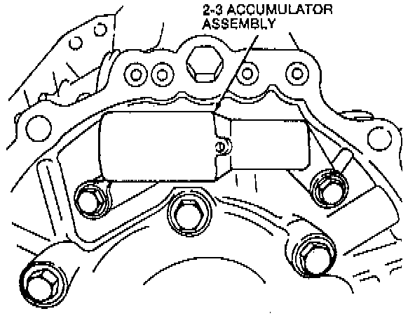
45. Install the 2-3 accumulator. Tighten the 2-3 accumulator bolts to 8-10 Nm (71-88 inch lbs.).
NOTE: Apply the specified ATF to the new lower accumulator seals before installing the 2-3 accumulator.
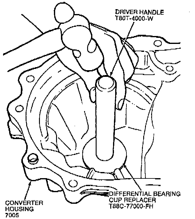
46. Use Driver Handle T80T-4000-W and Differential Bearing Cup Replacer T88C-77000-FH to install, the differential bearing shims and the differential bearing cup.
47. Install the differential.
48. Install the parking pawl and the parking pawl shaft.
49. Install the parking pawl return spring and parking pawl snap ring.
50. Install the parking lever actuating rod and parking lever actuating rod retainer.
51. Install the support. Tighten the park actuator support bolts to 11-13 Nm (96-121 inch lbs.).
52. Install the manual control lever, manual valve detent lever, manual control lever spacer, washer, and nut. Tighten the manual control lever nut to 42-54 (31-40 ft. lbs.).
53. Install the main control bracket. Tighten the main control bracket bolt to 8-10 Nm (71-88 inch lbs.).
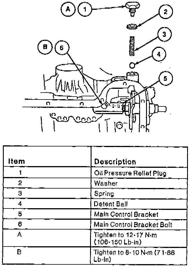
54. Install the detent ball, spring, washer, and the oil pressure relief plug. Tighten the oil pressure relief plug to 12-17 Nm (106-150 inch lbs.).
55. Verify that the parking pawl operates properly by turning the manual control lever.
56. Apply the specified ATF to the low/reverse clutch piston inner seal and low/reverse clutch piston outer seal of the low/reverse clutch piston.
57. Attach the Seal Protector T88C-77000-GH to the low/reverse clutch piston outer seal.
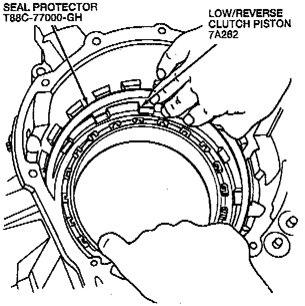
58. Install the low/reverse clutch piston by pushing evenly around the circumference. Remove the seal protector.
CAUTION: Be careful not to damage the low/reverse clutch piston outer seal.
59. Install the low/reverse clutch piston outer seal by pushing evenly around the circumference, being careful not to damage the low/reverse clutch piston outer seal.
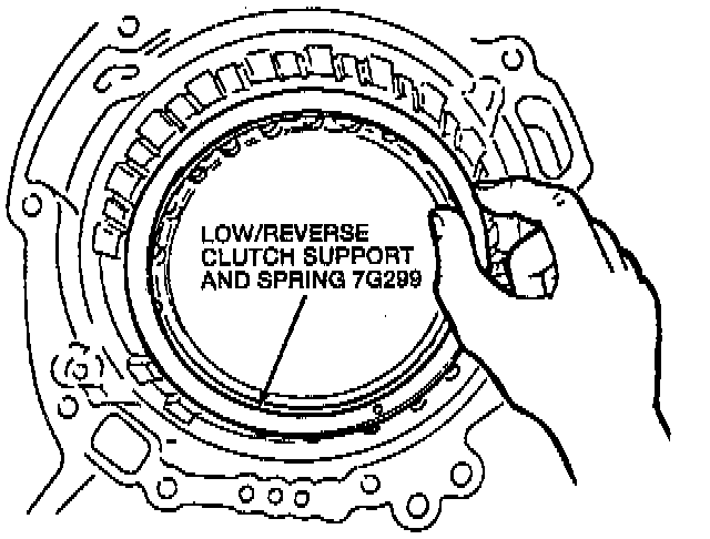
60. Install the low/reverse clutch support and spring.
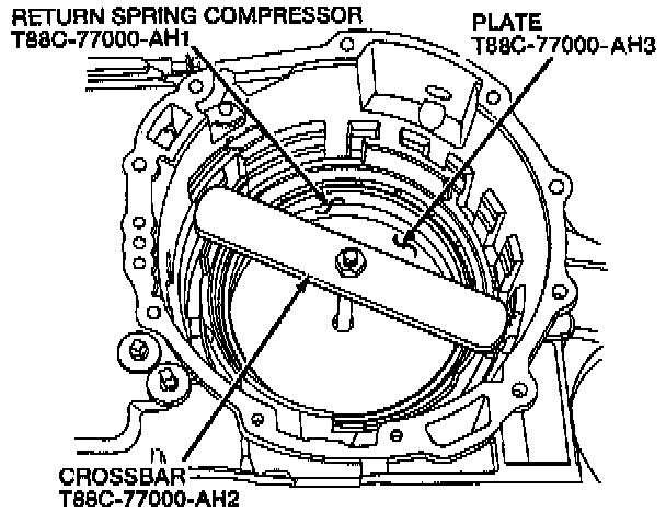
61. Use Return Spring Compressor T88C-77000-AH1 (part of T88C-77000-AH), the Crossbar T88C-77000-AH2 (part of T88C-77000-AH), and the Plate T88C-77000-AH3 (part of T88C-77000-AH) to compress the low/reverse clutch support and spring.
62. Install the retainer snap ring.
63. Remove the Return Spring Compressor.
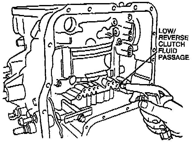
64. Pour the specified ATF over the low/reverse clutch piston until it is fully submerged. Check that no bubbles appear from between the low/reverse clutch piston and low/reverse clutch piston inner seal and low/reverse clutch piston outer seal when applying compressed air through the low/reverse clutch fluid passage.
CAUTION: The compressed air must be under 390 kPa (57 psi) and not applied for more than 3 seconds.
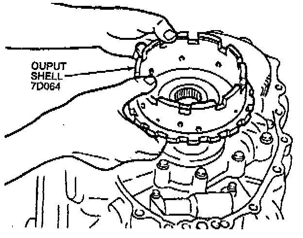
65. Install the output shell on the output gear.
66. Install the 71 mm (2.80 inch) final drive gear front thrust bearing and the planet gear bearing thrust washer onto the output shell.
NOTE: Be sure that the planet gear bearing thrust washer and final drive gear front thrust bearing are installed in the correct position.
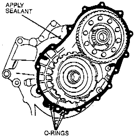
67. Apply a thin coat of Silicone Gasket and Sealant F6AZ-19562-AA or equivalent meeting Ford specification WSE-M4G323-A6 to the contact surfaces of the converter housing and Transaxle case.
68. Install new O-rings.
69. Install the Transaxle case on the converter housing. Install the 16 Transaxle case bolts. Tighten the Transaxle case bolts to 38-51 Nm (28-38 ft. lbs.).
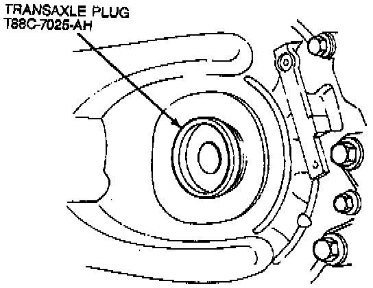
70. Install Transaxle Plug Set T88C-7025-AH on the differential side gears.
CAUTION: Failure to install the Transaxle plugs may allow the differential side gears to become positioned.
71. Place the 3-4 clutch assembly over the turbine shaft.
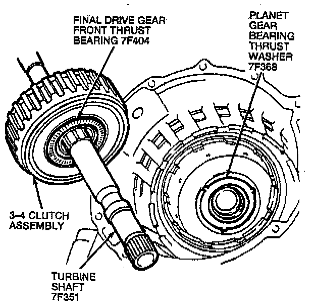
72. Install the turbine shaft and the 3-4 clutch assembly into the transaxle case.
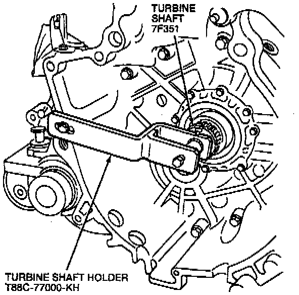
73. Install the Turbine Shaft Holder T88C-77000-KH and attach it to the turbine shaft.
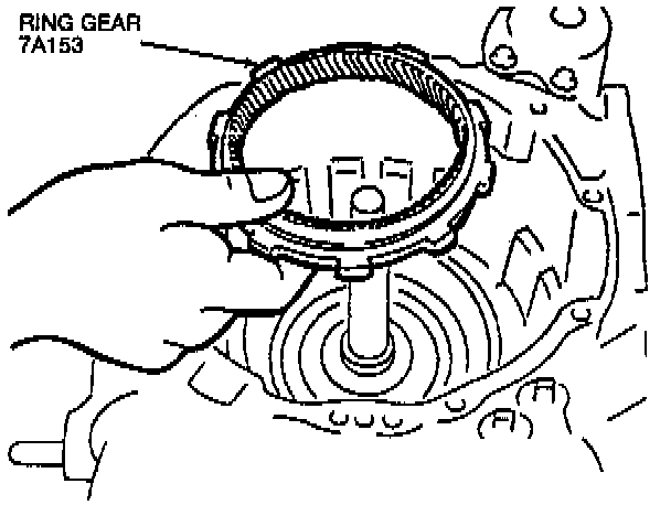
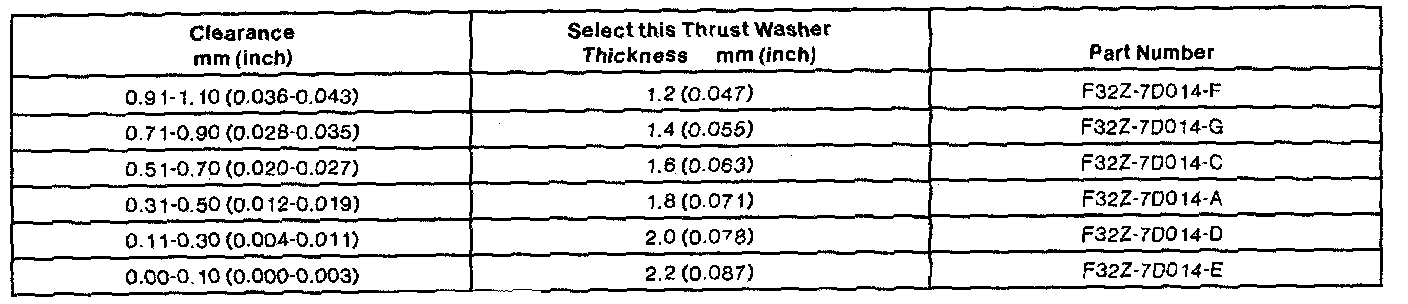
74. Install the ring near.
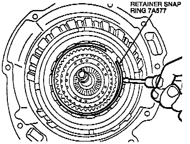
75. Install the retainer snap ring.
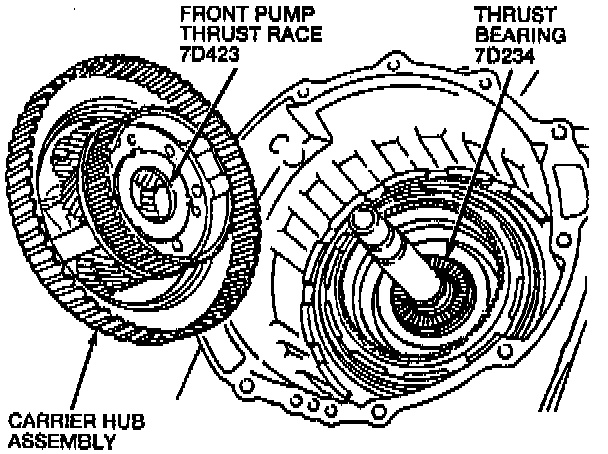
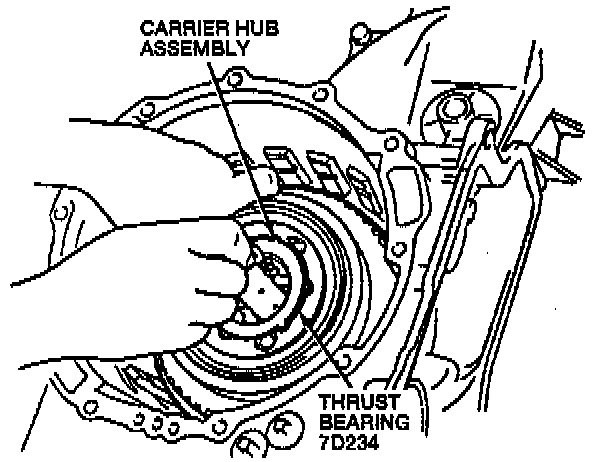
76. Install the carrier hub assembly.
NOTE:
^ Be sure the front pump thrust race and thrust bearing are in the correct position before installing the carrier hub assembly.
^ Hold the turbine shaft with one hand to prevent it from rotating. Install the carrier hub assembly into the 3-4 clutch assembly by rotating it.
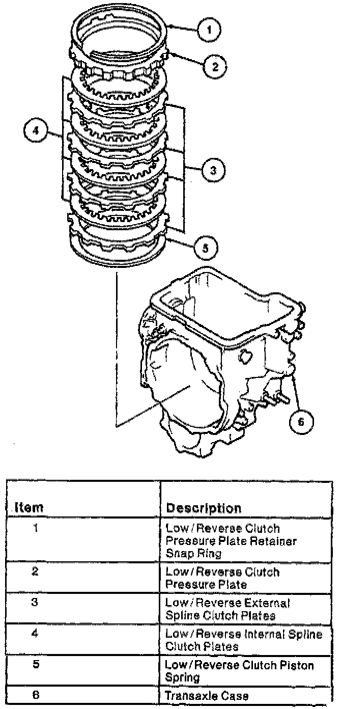
77. Install the low/reverse external clutch plates and low/reverse internal spline clutch plates, low/reverse clutch pressure plate, and low/reverse clutch pressure plate retainer snap ring.
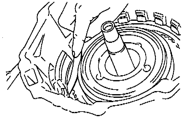
78. Measure the clearance between the low/reverse clutch pressure plate retainer snap ring and the low/reverse clutch pressure plate. The clearance should be 1.5-1.8 mm (0.059-0.071 inch). If the clearance is not within specification, adjust it by selecting a low/reverse clutch pressure plate with the appropriate thickness.
Pressure Plate: Part No.
6.8 mm (0.268 inch): E92Z-7B066-AD
7.0 mm (0.276 inch): E92Z-7B066-Y
7.2 mm (0.283 inch): E92Z-7B066-Z
7.4 mm (0.291 inch): E92Z-7B066-AA
7.6 mm (0.299 inch): E92Z-7B066-AB
7.8 mm (0.307 inch): E92Z-7B066-AC
79. Install the one-way clutch thrust washer.
80. Install the overrunning clutch outer race.
NOTE: Turning the carrier hub assembly counterclockwise eases the installation of the overrunning clutch outer race.
81. Install the retainer snap ring.
82. Install the servo piston spring and servo band piston to the Transaxle case.
83. Compress the servo band piston with a C-clamp and a socket.
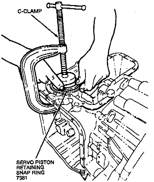
84. Install the servo piston retaining snap ring.
85. Remove the C-clamp and socket.
86. Install the piston stem and the servo rod nut. Do not tighten servo rod nut at this time.
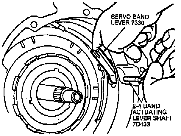
87. Install the servo band lever.
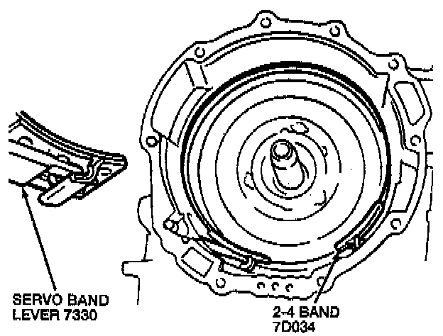
88. Install the 2-4 band in the Transaxle case so it is fully expanded.
NOTE: Interlock the 2-4 band and 2-4 band actuating lever shaft.
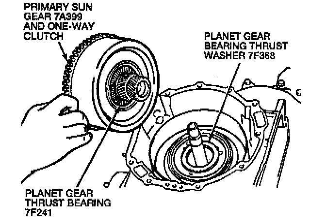
89. Install the primary sun gear and one-way clutch assembly by rotating it.
NOTE: Be sure the planet gear bearing thrust washer and planet gear thrust bearing are installed in the correct position.
90. Pull the 2-4 band with pliers and install the piston stem in the correct position. Tighten the piston stem by hand.

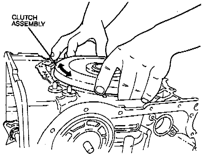
91. Install the clutch assembly by rotating it.
NOTE: Be sure the thrust washer is installed in the correct position before installing the clutch assembly.

92. Install the turbine shaft snap ring.
93. Remove the Turbine Shaft Holder.
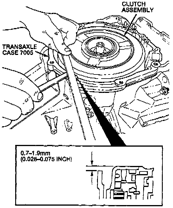
94. Measure the height between the clutch assembly and the transaxle case. The proper height should be 0.7-1.9 mm (0.0028-0.075 inch).
95. Place the forward planet thrust washer on the clutch assembly.
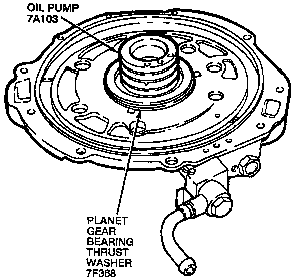
96. To adjust the total end play, remove the previous planet gear bearing thrust washer and oil pump gasket from the oil pump.
97. Place a 2.2 mm (0.087 inch) planet gear bearing thrust washer on the oil pump.
98. Set the oil pump onto the clutch assembly.
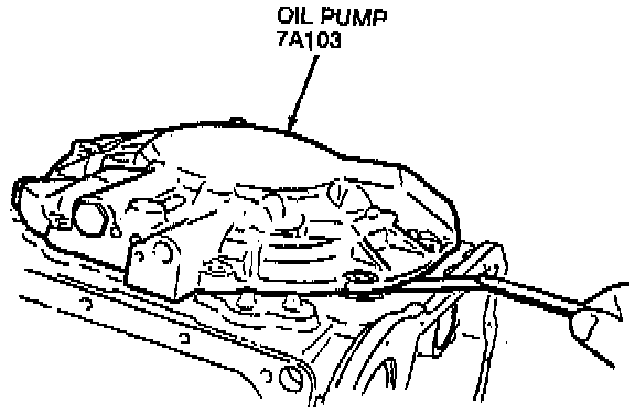
99. Measure the clearance between the Transaxle case and the oil pump.
100. Take several measurements and calculate the average gap.
101. Select a suitable planet gear bearing thrust washer from the chart.
102. Remove the oil pump.
103. Place the selected planet gear bearing thrust washer, planet gear thrust bearing and a new oil pump gasket on the oil pump.
104. Install the oil pump onto the Transaxle. Tighten the ten oil pump bolts to 19-25 Nm (14-18 ft. lbs.).
105. Loosen the servo rod nut and tighten the piston stem to adjust the 2-4 band. Tighten the piston stem to 11-14 Nm (105-130 inch lbs.).
106. Loosen the piston stem 1.5 turns counterclockwise.
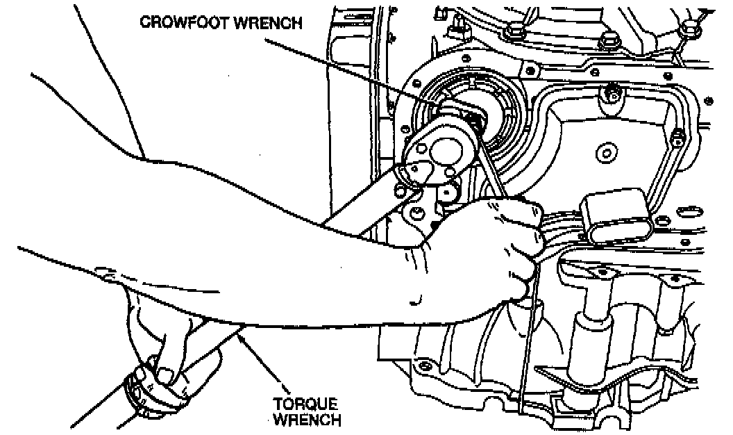
107. Secure the piston stem with a wrench and using a torque wrench and a crowfoot, tighten the servo rod nut to 25-39 Nm (19-28 ft. lbs.).
108. Install the oil pan screen with a new oil pan screen ring to the Transaxle. Tighten the oil pan screen bolts to 8-10 Nm (71-88 inch lbs.).
109. Install the transmission fluid pan with a new gasket. Tighten the transmission oil pan bolts to 8-10 Nm (71-88 inch lbs.).
NOTE: Make sure the oil pan magnet is properly positioned in the transmission fluid pan.
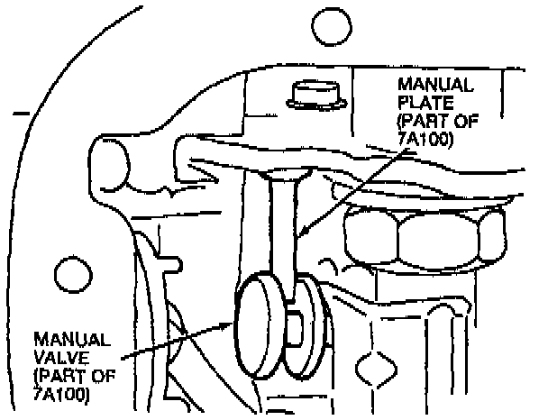
110. Align the manual valve with the pin on the manual valve detent lever.
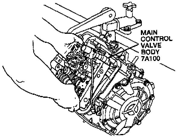
111. Install a new main control cover gasket and the main control valve body in the Transaxle case.
112. Tighten the main control valve body bolts to 11-14 Nm (97-130 inch lbs.).
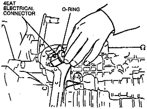
113. Install the electrical connector with a new O-ring in the transaxle case.
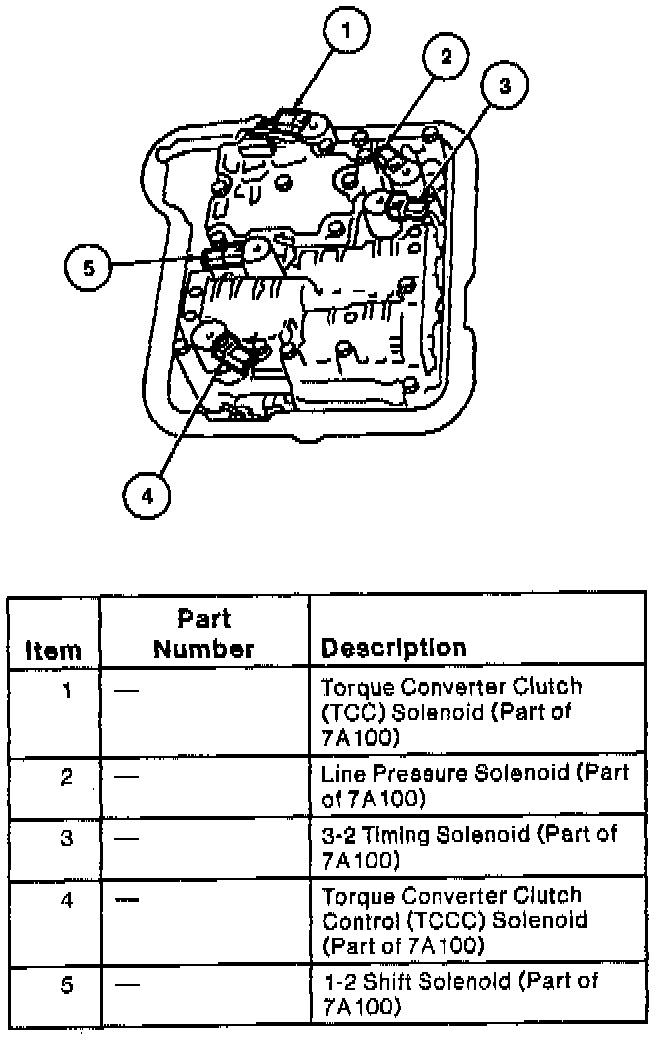
114. Match the shift solenoid connector coded colors and connect the shift solenoid connectors and the transmission fluid temperature (TFT) sensor connector.
115. Install the main control cover along with a new main control cover gasket. Tighten the main control cover bolts to 8-10 Nm (71-88 inch lbs.).
116. Install the steel ball, converter drain-back valve spring, fluid cooler tube and washer.
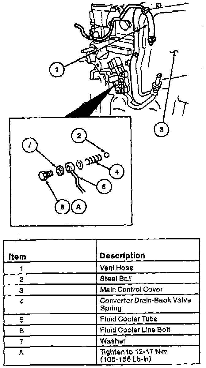
117. Install the oil cooler line bolt. Tighten the oil cooler line bolt to 12-17 Nm (105-156 inch lbs.).
118. Install the vent hose on the main control cover.
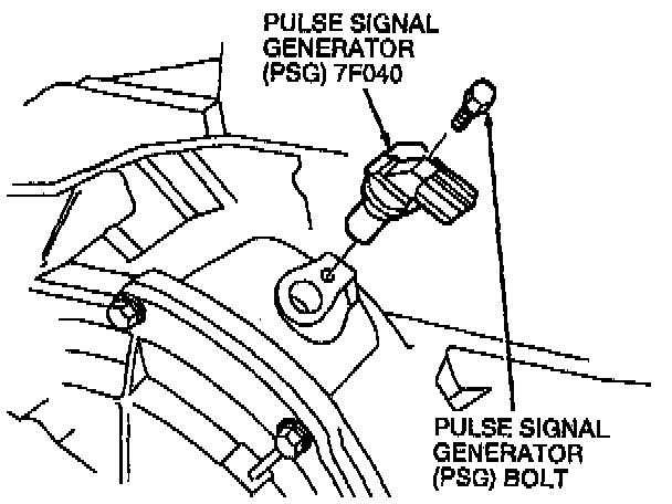
119. Install the pulse signal generator (PSG). Tighten the PSG bolt to 8-10 Nm (71-88 inch lbs.).
120. Install the transmission range (TR) switch.
121. Adjust the TR switch.
122. Tighten the TR switch bolts to 8-10 Nm (71-88 inch lbs.).
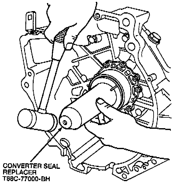
123. Use Converter Seal Replacer T88C-77000-BH to install a new converter impeller hub seal.
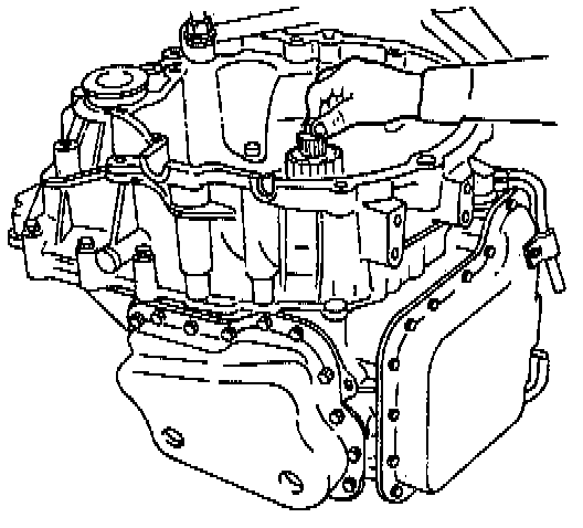
124. Install the oil pump shaft.
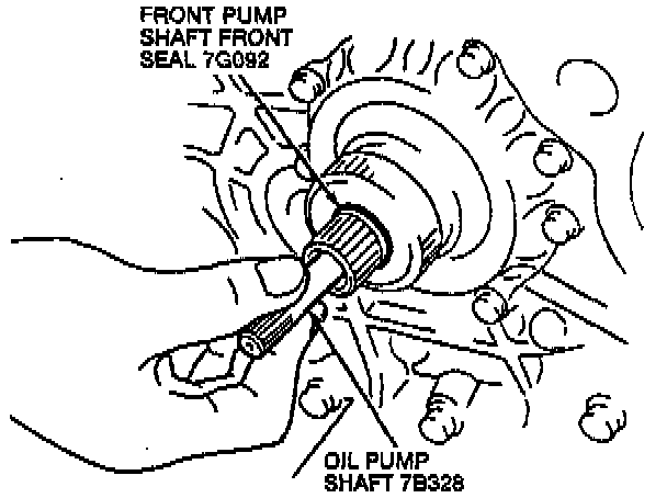
125. Install a new front pump shaft front seal onto the oil pump shaft.
126. Fill the torque converter with specified automatic transmission fluid (ATF).
127. Install the torque converter into the converter housing while rotating it to align the splines.
CAUTION: Do not force the torque converter in. Install it carefully.
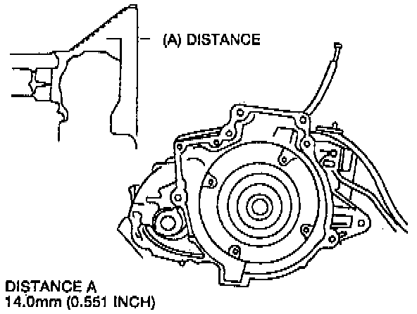
128. Measure the distance between the torque converter and the edge of the converter housing. The proper distance should be 14.0 mm (0.551 inch).