Disassembly
NOTE: Position the Transaxle on the bench mount in its normal upright position. This will prevent used automatic transmission fluid (ATF) from flowing through the Transaxle and causing any sediment in the transmission fluid pan to contaminated the Trans axle components.1. Mount the Transaxle on a Bench Mounted Holding Fixture T57L-500-B.
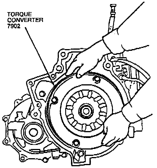
2. Remove the torque converter.
CAUTION: The torque converter is heavy. Be careful not to drop it.
3. Position a drain pan under the Transaxle.

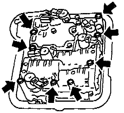
4. Slowly loosen the transmission oil pan mounting bolts, working from the front LH corner to the rear allowing the transmission fluid pan to gradually drop and the automatic transmission fluid (ATF) to drain slowly.
5. When all the ATF has been drained remove and thoroughly clean the transmission fluid pan. Discard the oil pan to case gasket.
6. Inspect the ATF.

7. Remove and discard the oil pan screen and oil pan screen ring.
CAUTION: DO NOT reuse or clean the oil pan screen. The filter element material will contaminate the Transaxle.

8. Remove the oil pump shaft.
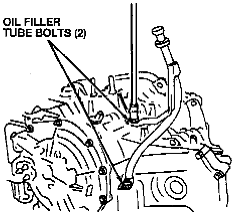
9. Remove the two oil filler tube bolts and pull the oil filler tube from its slot.

10. Remove the transmission range (TR) switch.
11. Remove the pulse signal generator (PSG).
12. Remove the vent hose.
13. Remove the fluid cooler line bolt, washers, and fluid cooler tube.
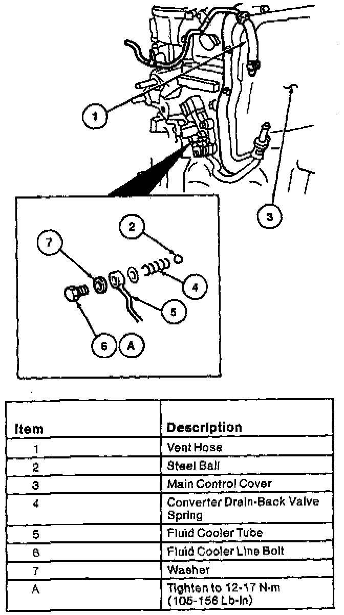
14. Use a pencil magnet to remove the converter drain-back valve spring and steel ball.
15. Remove the main control cover. Discard the main control cover gasket.
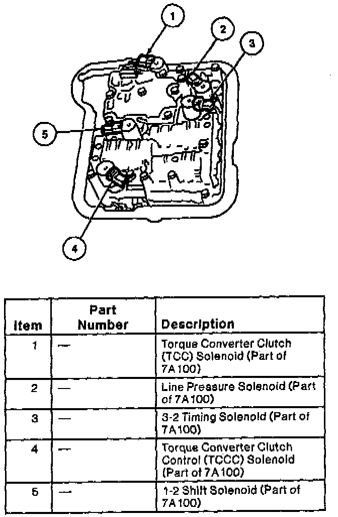
16. Disconnect the solenoid connectors. Note the position of the connectors to ease installation.
NOTE: The solenoid connectors are color coded to ease installation.
17. Disconnect the transmission fluid temperature (TFT) sensor connector.
13. Remove the 4EAT electrical connector from the transaxle case. Discard the O-ring.
19. Remove the eight main control valve body bolts.
20. Remove the main control valve body. Discard the main control cover gasket.

21. Remove the ten oil pump bolts.

22. Remove the oil pump, oil pump gasket, and planet gear thrust bearing. Discard the oil pump gasket.

23. Remove the turbine shaft snap ring.

24. Remove the clutch assembly and thrust bearing.
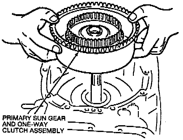
25. Remove the primary sun gear and the one-way clutch assembly.
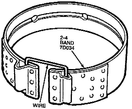
26. Remove the 2-4 band.
NOTE: Secure the 2-4 band with a small piece of wire to keep the 2-4 band from stretching.

27. Pull the 2-4 band actuating lever shaft while holding the servo band lever, then remove the servo band lever.
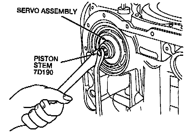
28. Use a wrench to secure the piston stem and loosen the piston stem locknut. Remove the piston stem from the servo assembly.

29. Use a C-clamp and socket to compress the servo band piston. Remove the servo piston retaining snap ring, servo and servo piston spring.
30. Remove the C-clamp.

31. Remove the retainer snap ring.
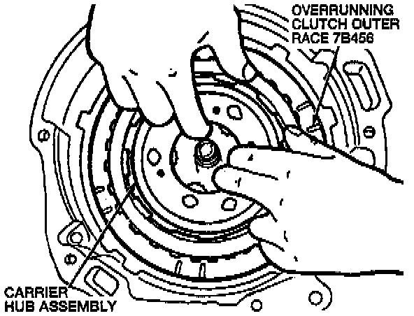
32. Remove the overrunning clutch outer race and carrier hub assembly.
33. Remove the wave washer.
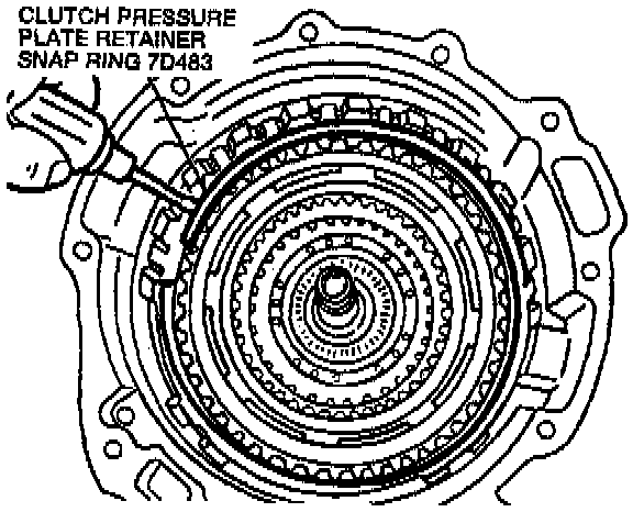
34. Remove the clutch pressure plate retainer snap ring.
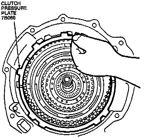
35. Remove the clutch pressure plate, the external spline clutch plate, and internal clutch plates.
CAUTION: The composition clutch plates, valve body gaskets, bands, and synthetic seals should not be cleaned in a vapor degreaser, or with any type of detergent solution. To clean these parts wipe them off with a lint-free cloth. New clutch plates or bands should be soaked in the specified automatic transmission fluid (ATF) for two hours before being assembled.
Clean the metal components with a suitable solvent and use compressed air to dry all parts and clean fluid passages.
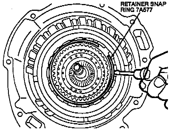
36. Remove the retainer snap ring.
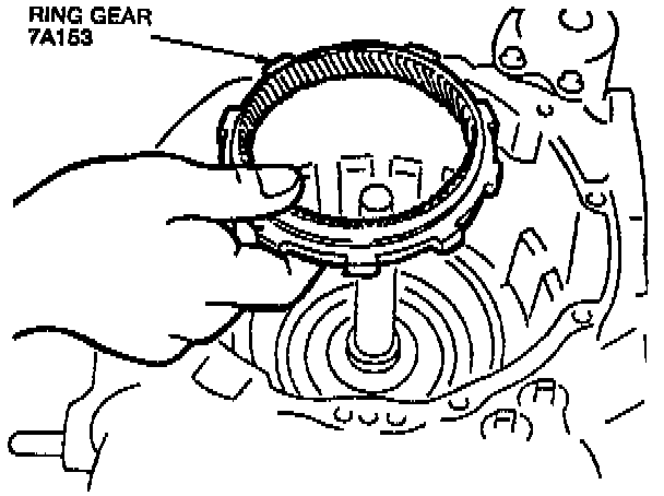
37. Remove the ring gear from the output shell.
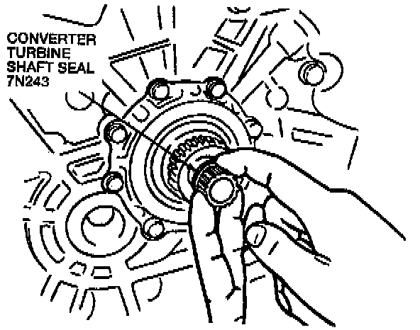
38. Remove the converter turbine shaft seal from the turbine shaft, located on the converter side of the transaxle case. Discard the converter turbine shaft seal.
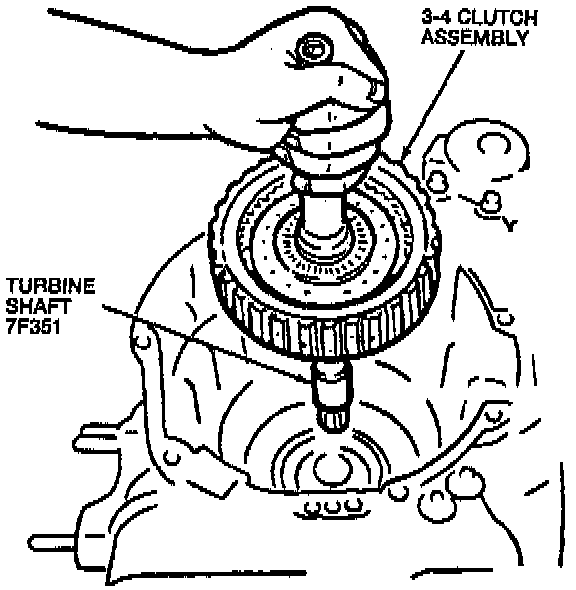
39. Pull the turbine shaft and remove the 3-4 clutch assembly.
40. Slide the 3-4 clutch assembly off of the turbine shaft.
41. Remove the 16 Transaxle case bolts securing the two halves of the Transaxle.
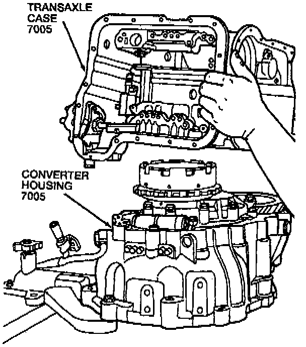
42. Split the Transaxle. Discard the O-rings.
NOTE: Use a plastic hammer if tapping is required to separate the transaxle halves.
43. Remove the planet gear bearing thrust washer and final drive gear front thrust bearing from the output shell.
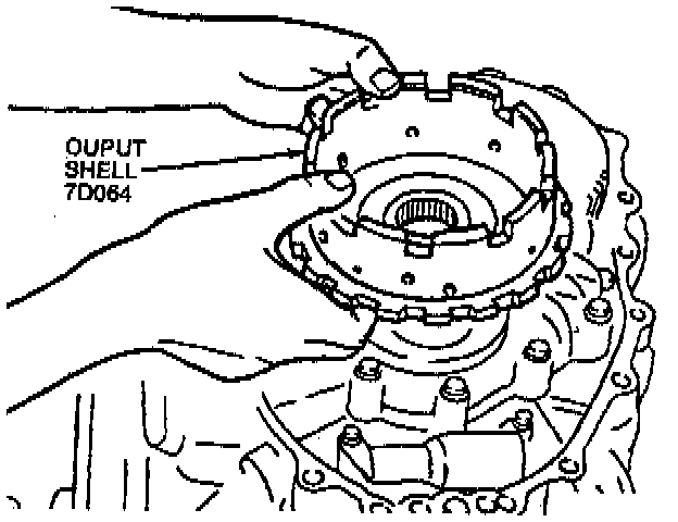
44. Remove the output shell from the output gear.

45. Use Return Spring Compressor T88C-77000-AH1 (part of T88C-77000-AH), Crossbar T88C-77000-AH2 (part of T88C-77000-AH), and Plate T88C-77000-AH3 (part of T88C-77000-AH) to remove the low/reverse clutch assembly.
46. Compress the low/reverse clutch support and spring. Compress only enough to remove the retainer snap ring.
47. Remove the retainer snap ring, then the low/reverse clutch support and spring.
NOTE: Do not deform the low/reverse clutch support and spring when removing it.
48. Remove the return spring compressor.
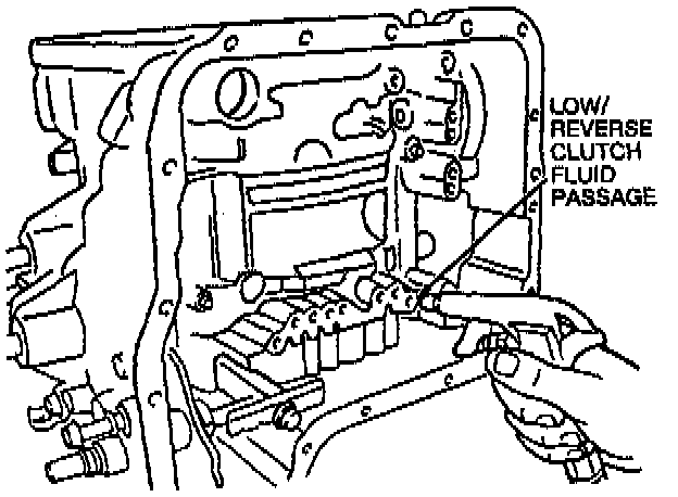
49. Apply compressed air, at a maximum of 390 kPa (57 psi), through the low/reverse clutch fluid passage to remove the low/reverse clutch piston.
50. Remove the oil pressure relief plug washer, spring, and detent ball.
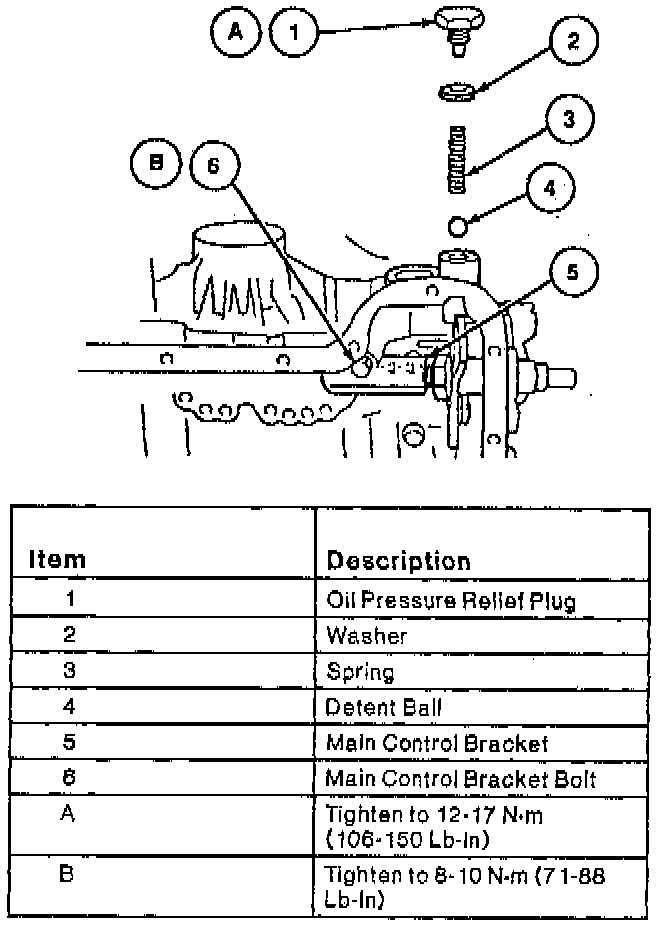
51. Remove the main control bracket.
52. Loosen the nut and pull the manual control lever out.

53. Remove the manual control lever nut, washer, spacer, and manual valve detent lever.
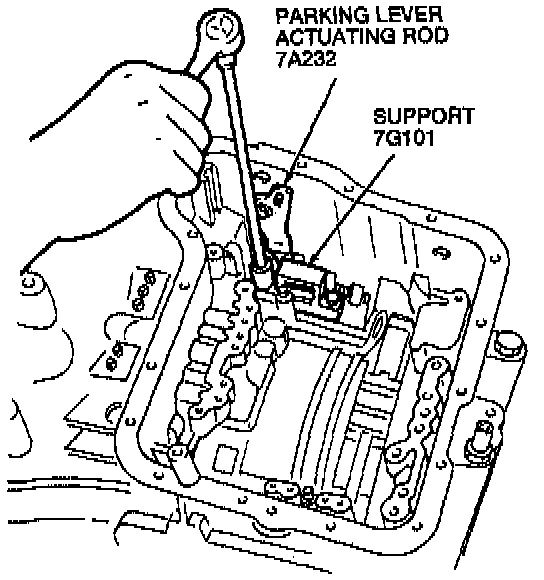
54. Remove the support.
55. Remove the parking lever actuating rod retainer.
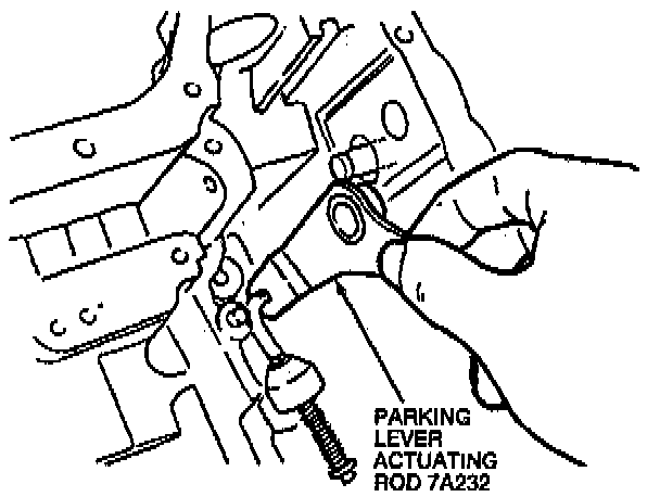
56. Remove the parking lever actuating rod.
57. Remove the parking pawl snap ring.
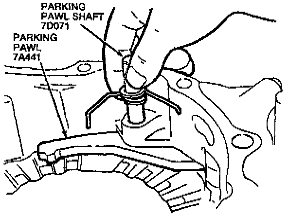
58. Pull the parking pawl shaft, then remove the parking pawl return spring and parking pawl.
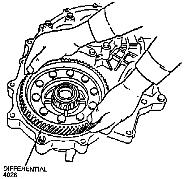
59. Remover the differential.
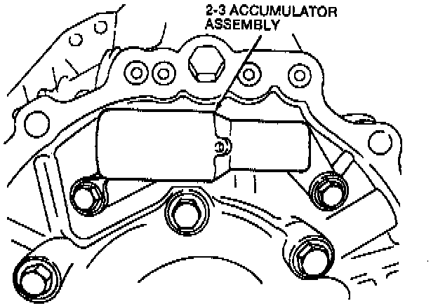
60. Remove the two accumulator bolts and remove the 2-3 accumulator assembly.
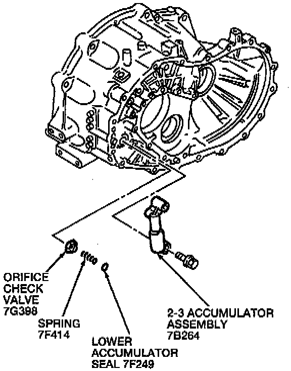
61. Remove the orifice check valve, spring, and lower accumulator seal. Discard the lower accumulator seal.
62. Remove the bearing housing bolt to access the roll pin.
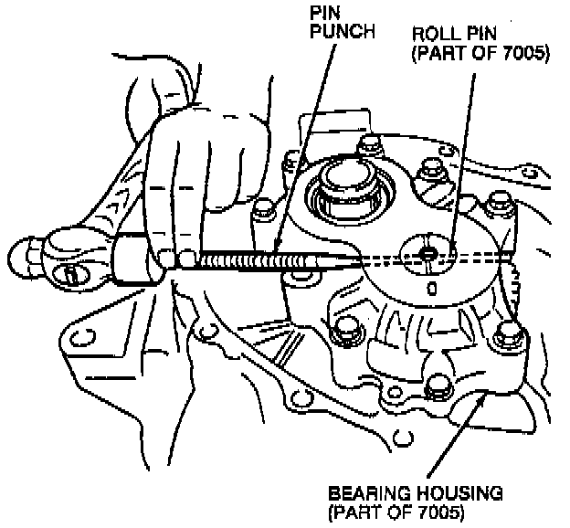
63. Use a pin punch and remove the roll pin. Discard the roll pin.
64. Remove the bearing housing. If necessary, lightly tap on the housing with a plastic hammer or a suitable tool.
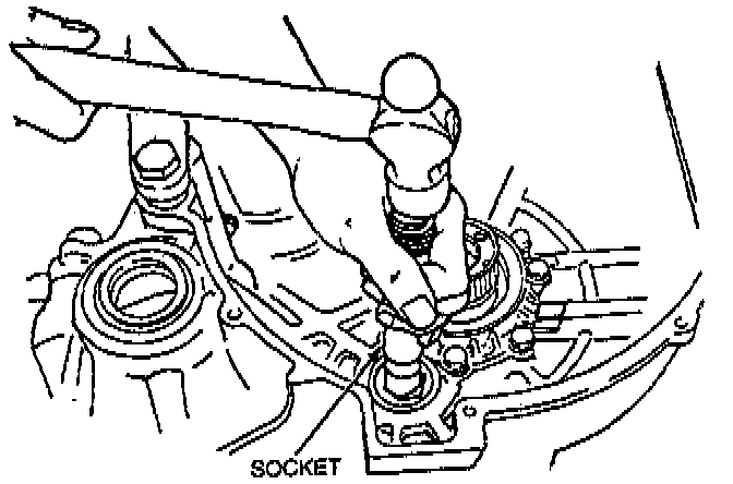
65. Use a socket to tap out the idler gear and output gear assemblies from the converter housing.
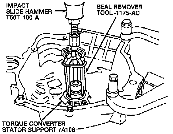
66. Use Seal Remover T50T-1175-AC and Impact Slide Hammer T50T-1 00-A to remove the converter impeller hub seal from the torque converter stator support.
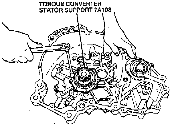
67. Remove the eight torque converter stator support bolts.
68. Remove the converter housing from the Transaxle holding fixture.
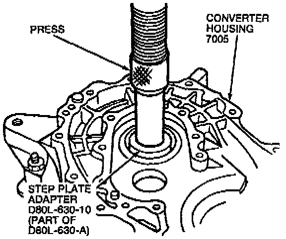
69. Use Step Plate Adapter D80L-630-10 (part of D80L-630-A) or equivalent to press the torque converter stator support out of the converter housing.
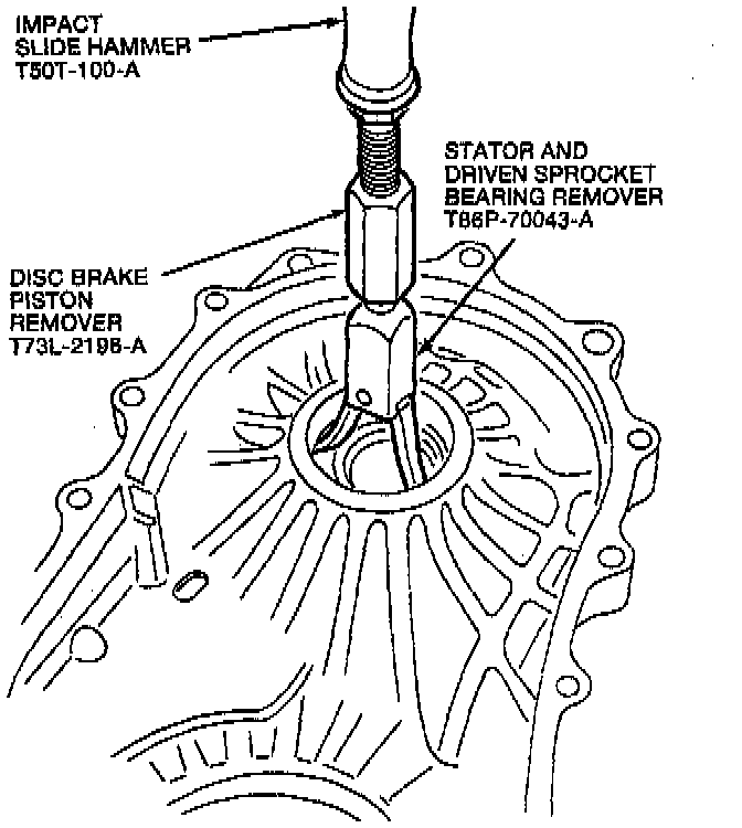
70. Use Stator and Driven Sprocket Bearing Remover T86P-70043-A, Disc Brake Piston Remover (73L-2196-A), and Impact Slide Hammer T50T-100-A to remove the differential.
71. Remove the output shaft bearing selective shim.
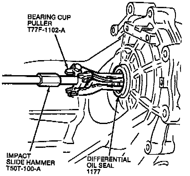
72. Use Bearing Cup Puller T77F-1102-A and Impact Slide Hammer T5OT-100-A to remove the differential oil seal.