Assembling Sub-Assemblies
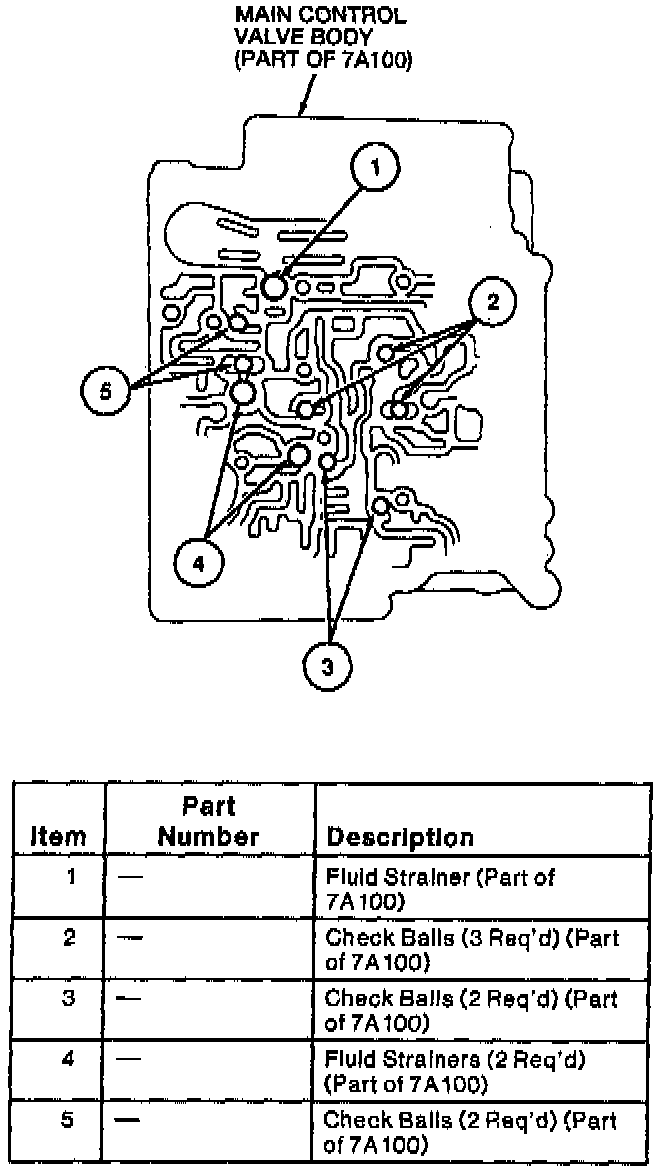
1. Install the three fluid strainers and seven check balls into the main control valve body.
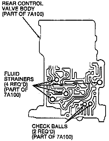
2. Install the four fluid strainers and two check balls into the rear control valve body.
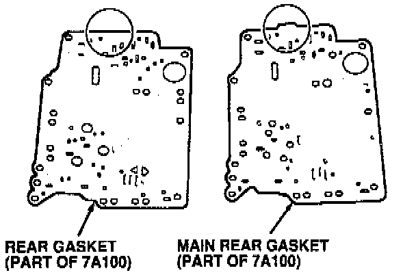
3. Install the new main rear gasket, rear separator plate, and new rear gasket on the rear control
CAUTION: Do not confuse the main rear gasket with the rear gasket.
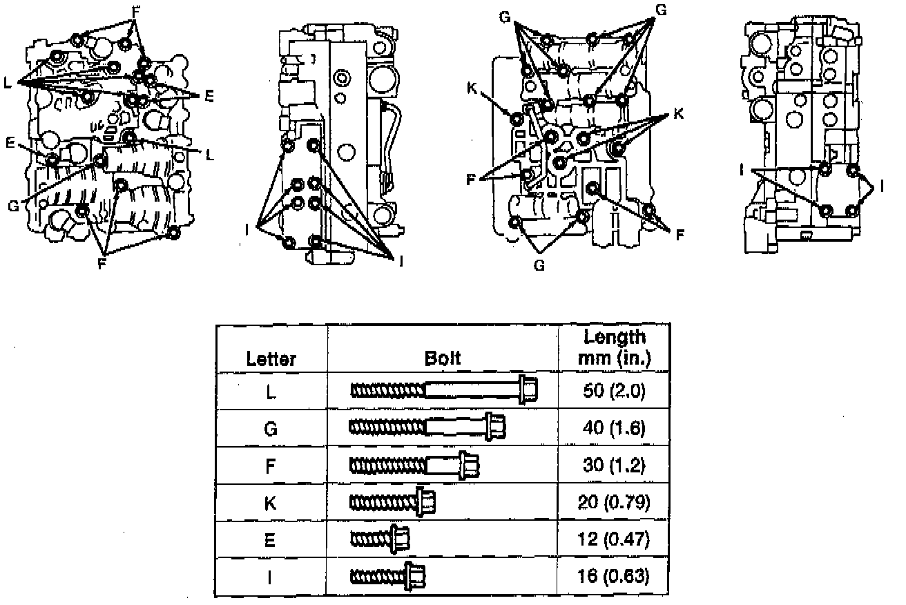
4. Install the rear control valve body onto the main control valve body.
NOTE: Match the bolt head letters to the letters on the rear valve body.
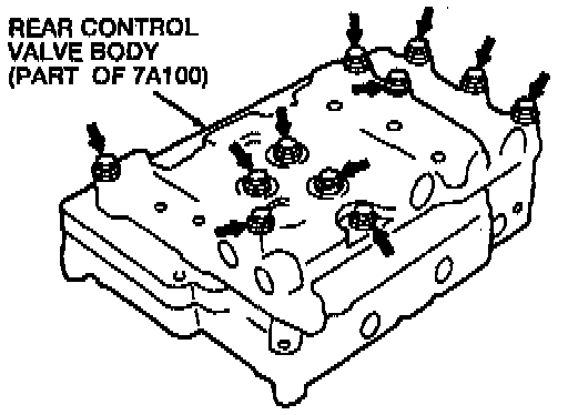
5. Hand tighten the indicated bolts.
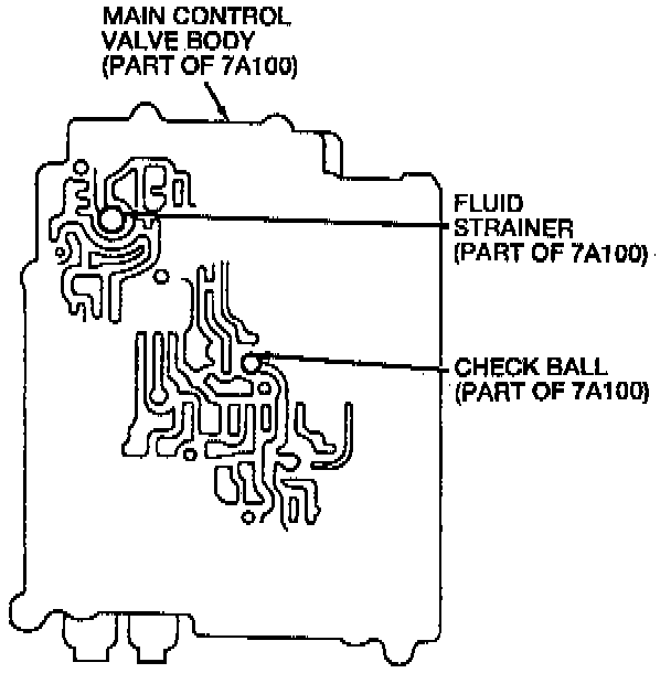
6. Install the fluid strainer and check ball into the main control valve body.
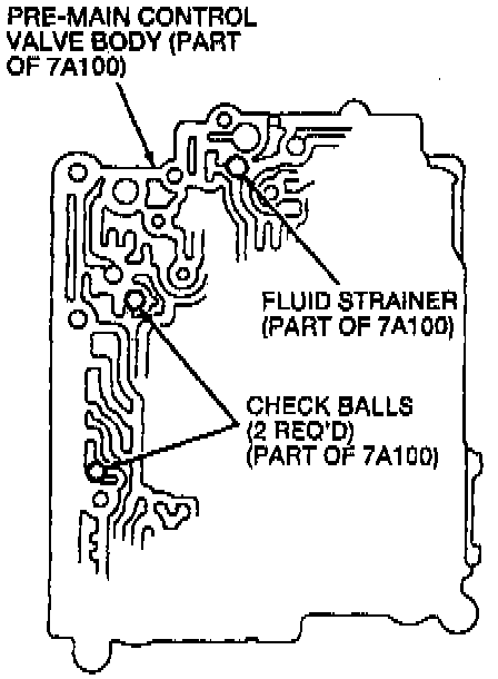
7. Install the fluid strainer and two check balls into the pre-main control valve body.
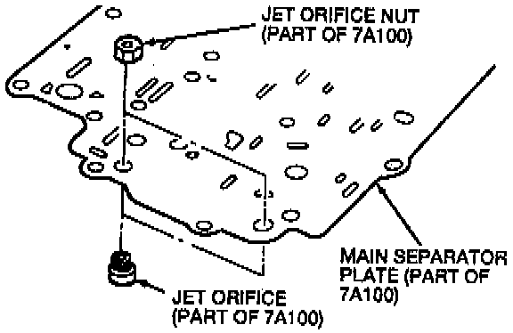
8. Install the jet orifices and jet orifice nuts to the main separator plate. Tighten the jet orifice nuts to 1.7-2.2 Nm (15-19 inch lbs.).
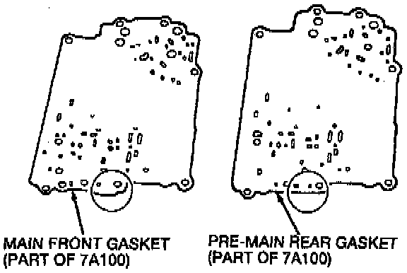
9. Install a new pre-main rear gasket, a new main front gasket, and the main separator plate on the-main control valve body.
CAUTION: Do not confuse the main front gasket and the pre-main rear gasket.
10. Install the pre-main control valve body onto the main control valve body.
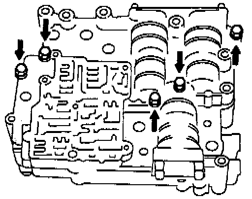
11. Hand tighten the bolts.
NOTE: Match the bolt head letters to the letters on the valve body.
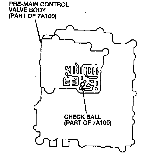
12. Install the check ball into the pre-main control valve body.
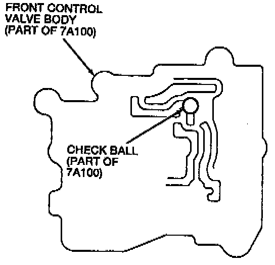
13. Install the check ball into the front control valve body.
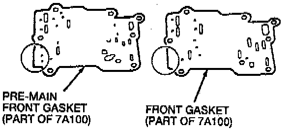
14. Install a new pre-main front gasket, front separator plate, and a new front gasket on the front control valve body.
CAUTION: Do not confuse the pre-main front gasket and the front gasket.
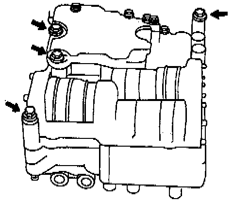
15. Align the valve bodies using the four bolts as shown.
16. Install the front control valve body onto the pre-main control valve body.
NOTE: Match the bolt head letters to the main valve body letters as shown. Hand tighten the bolts.
17. Tighten all of the valve body bolts to 6.5-7.8 Nm (58-69 inch lbs.).
18. Install the fluid strainers.
19. Apply automatic transmission fluid (ATF) to the new solenoid O-rings and install the following solenoids:
^ Line pressure solenoid
^ Torque converter clutch (TCC) solenoid
^ 3-2 timing solenoid
^ 1-2 shift solenoid
^ Torque converter clutch control (TCCC) solenoid
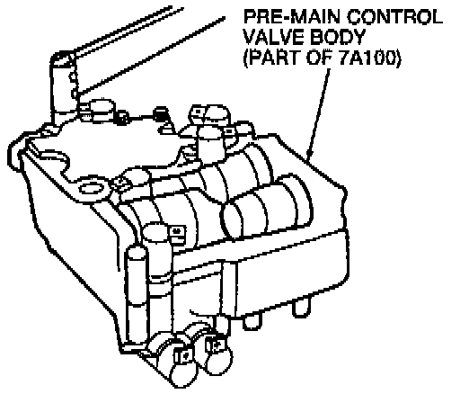
20. Tighten the solenoid bolts to 6.5-7.8 Nm (58-69 inch lbs.).
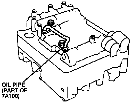
21. Apply ATF to the oil pipe O-rings and install the oil pipe. Tighten the oil pipe bolts to 6.5-7.8 Nm (58-69 inch lbs.).
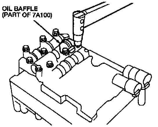
22. Install the oil baffle. Tighten the oil baffle bolts to 6.5-7.8 Nm (58-69 inch lbs.).
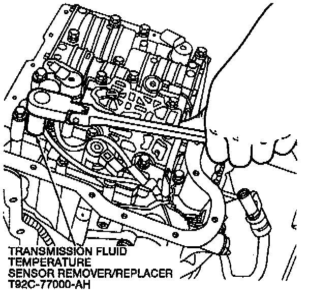
23. Use Transmission Fluid Temperature Sensor Remover/Replacer T92C-77000-AH to install the TFT sensor. Tighten the TFT sensor to 8-10 Nm (71-88 inch lbs.).